MagnaTrack S
EN
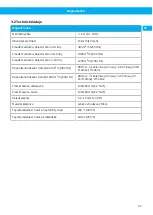
5
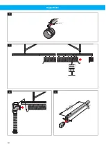
Check the airflow in the nozzle opening with an
airflow indicator.
• Engine size 0 - 4 litre: (400 m
3
/h, 250 cfm)
• Engine size > 4 - 10 litre: (1000 m
3
/h, 600 cfm)
• Engine size > 10 litre: (1200 m
3
/h, 700 cfm)
• If required, check the fan impeller rotation direc-
tion and/or damper function.
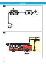
6
Check the electrical installation (disconnection
box, micro switch, magnet) according to the wiring
diagram.
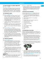
4.10 Fans
Fans are not included in the basic package. For the
best results, one fan per extraction unit is recommen-
ded. It is also possible to connect several units to a
central fan.
To get negative pressure in the ducting system and
avoid exhaust leakage, the fan is to be positioned as
near the duct outlet from the room as possible.
Please contact your Nederman representative for ad-
vice on fan selection.
NOTE!
A lockable safety switch is recommended for
the electrical system including the fan.
4.10.1 Recommended pressure drops and
air flows
• 800 Pa + 45 Pa/m rail at 1000 m3/h (3.2 in.wg +
0.055 in.wg/ft) of track at 600 cfm (6" nozzle).
• 800 Pa + 30 Pa/m rail at 600 m3/h (3.2 in.wg +
0.037 in.wg/ft) of track of 400 cfm (5" nozzle).
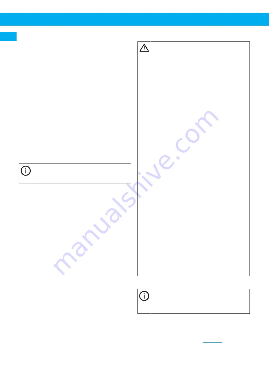
5 Using
WARNING! Risk of personal injury
• The system must only be used in combination
with the anchor plate which should be moun-
ted on the vehicle.
• Do not extract hot, burning or ignited mater-
ial or substances that might react with parts
or materials from the suction system.
• The system must not be used when working
on the vehicle´s fuel system, when rechar-
ging the batteries or whenever there is a risk
for inflammable dust or explosive gases.
• The system must be disconnected and must
not be exposed for water when washing the
vehicle.
• The system is designed for use only in the
direction of the length of the rail.
• The system must not be used for other pur-
poses than extracting exhausts.
• Check that there is enough suction capacity
in the extraction unit before it is connected
to the vehicle’s exhaust pipe. If not, check the
fan impeller rotation direction and/or damper
function. If necessary check the installation
of the fan start switch.
• Check that the nozzle is correctly fitted to
the exhaust pipe after the vehicle has been
moved.
• Check that the hose or nozzle will not snag on
any protruding parts on the vehicle.
• Repair of damaged cables or other electric-
al components should be done by a qualified
electrician. If the power cable failed, please
replace only with the same type.
• The flexible hose can withstand 150 °C (300
°F) for continuous running and 180 °C (355
°F) for short periods. Use at higher temper-
atures will shorten the life of the product.
Therefore, avoid tasks that require exten-
ded periods of continuous running which will
generate high exhaust temperatures.
5.1 Connection
NOTE!
The hose should always be connected to the
exhaust pipe while the vehicle is parked in the
station.
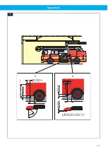
1
Open the station door and start the exhaust ex-
traction fan (as an alternative the fan can be con-
nected to an automatic start/stopsystem).
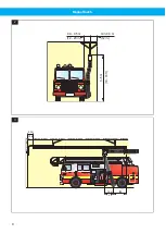
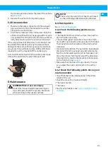
2
Reverse the vehicle in so that the exhaust pipe is
just at the station door, see
.
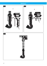
3
Locate the nozzle of the flexible hose on the ex-
haust pipe. Fasten the electromagnetic unit onto
20
Summary of Contents for MagnaTrack S
Page 8: ...MagnaTrack S 0 3 0 5 m min 0 3 m 3 5 m 12 20 in 12 in 10 16 ft 2 1 0 m 3 ft A 0 3 m 12 in 3 8...
Page 10: ...MagnaTrack S M8 x 12 6 7 8 m min 0 8 m in 2 5 ft 9 10...
Page 12: ...MagnaTrack S 1 A 11 1 B 12 13 12...
Page 13: ...MagnaTrack S 1 2 2 14 A B1 B2 15 13...
Page 14: ...MagnaTrack S PE 2 3 4 5 6 7 8 9 10 12 11 1 16 max 1 m max 3 ft 17 14...
Page 95: ...www nederman com...


