

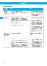

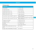

MagnaTrack S
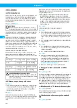
4.4 Płyta kotwiąca do dyszy standardo-
wej
Patrz
Płytę kotwiącą należy zamontować do boku pojazdu
zgodnie z wymiarami podanymi na rysunku.
4.5 Płyta kotwiąca do dyszy model HB
Patrz
Płytę kotwiącą należy przymocować z boku pojazdu,
w odległości 600 mm (23.6 in) lub 900 mm (35.4 in) od
rury wydechowej. W razie potrzeby odległość tę moż-
na zmienić (+100 mm, -25 mm / +4 in, -1 in)) luzując
śrubę regulacyjną elektromagnesu.
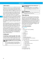
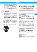
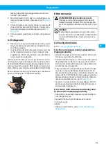
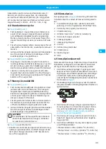
4.6 Dysza standardowa
Patrz rysunki 1 i 2.
1
Zamontować zamek łańcuchowy do elektroma-
gnesu, jak pokazano na rysunku. Zamocować wąż
w jednostce elektromagnetycznej za pomocą opa-
ski zaciskowej do węża i przykryć gumowym pier-
ścieniem. Sprawdzić, czy dysza, gdy nie jest pod-
łączona do pojazdu, jest skierowana do przodu w
kierunku jazdy.
2
Aby wyregulować siłę sprężyny w dyszy po za-
montowaniu płyty kotwiącej, należy użyć śruby re-
gulacyjnej oznaczonej numerem 1.
3
W razie potrzeby wyreguluj długość elastycznego
przewodu tak, aby dysza znajdowała się w wyma-
ganej pozycji i przymocuj szybkozłącze w jednost-
ce elektromagnetycznej.
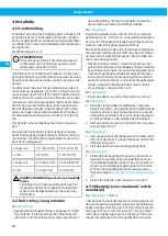
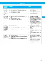
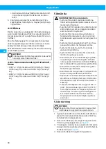
Patrz
pozycja A.
1
W otworze dyszy standardowej znajdują się dwie
podkładki wyładowcze (cierne), jedna wykonana
ze stali (2), druga z gumy (1). Podkładka stalowa
(2) musi być najbardziej z przodu patrząc w sto-
sunku do kierunku jazdy pojazdu do przodu.
2
Umieścić dyszę na rurze wydechowej i zamoco-
wać elektromagnes do płyty kotwiącej, upewnia-
jąc się, że wąż jest prawidłowo napięty. Wąż powi-
nien tworzyć zgięcie 90° wychodzące z rury wyde-
chowej.
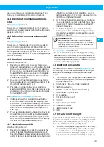
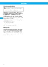
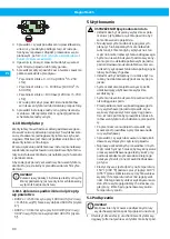
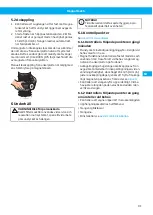
4.7 Dysza model HB
Patrz rysunki 1 i 2.
1
Zamontować sprężynę listkową dyszy w elektro-
magnesie za pomocą śruby regulacyjnej, jak po-
kazano na rysunku. Zamontować wąż w elektro-
magnesie za pomocą opaski zaciskowej do wę-
ża i przykryć gumowym pierścieniem. Sprawdzić,
czy dysza, gdy nie jest podłączona do pojazdu, jest
skierowana do przodu w kierunku jazdy.
2
Aby wyregulować dyszę po zamontowaniu płyty
kotwiącej, należy użyć śruby regulacyjnej ozna-
czonej numerem 1, aby przesunąć sprężynę listko-
wą nieco w górę lub w dół.
3
W razie potrzeby wyreguluj długość elastycznego
przewodu tak, aby dysza znajdowała się w wyma-
ganej pozycji i przymocuj szybkozłącze w jednost-
ce elektromagnetycznej.
UWAGA!
Jeśli sprężyna listkowa zostanie przesunięta do
góry, nie może się stykać z górnym wężem. W
razie potrzeby należy odciąć jej górny koniec.
pozycja B1 lub B2.
• Umieścić dyszę na rurze wydechowej i zamocować
elektromagnes do płyty kotwiącej, upewniając się,
że wąż jest prawidłowo napięty. Wąż powinien two-
rzyć zgięcie 90° wychodzące z rury wydechowej.
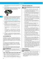
4.8 Instalacja elektryczna
siecią zasilającą musi zostać wykonane przez wykwali-
fikowanego elektryka.
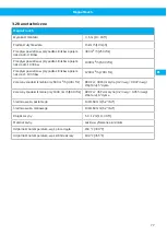
1
Transformator (nie wchodzi w skład zestawu). Na-
pięcie wtórne: 24V AC. Stopień ochrony IP54. Moc:
5VA.
2
Wyłącznik serwisowy (niedołączony)
3
Zasilanie
4
H05RN-F 3G 1,5 mm
2
(USA: SJ 3 x AWG 15)
5
Wąż poziomy z kablem
6
Skrzynka rozłączeniowa
7
Magnes rozłączający
8
24 V DC
9
Wąż pionowy z kablem
10 Wyłącznik
11 Elektromagnesie
12 VDR
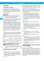
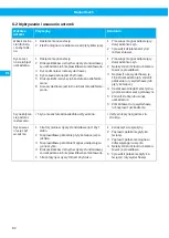
4.9 Lista kontrolna instalacji
Po zakończeniu montażu mechanicznego, podłączania
wentylatorów i instalacji elektrycznej system Magna-
Track S jest gotowy do użycia po dwukrotnym spraw-
dzeniu następujących punktów:
1
Sprawdzić przebieg procedury odłączania. Wąż
odciągowy powinien odłączyć się od rury wyde-
chowej bezpośrednio przed otwarciem drzwi sta-
cji przy normalnej prędkości, nie więcej niż 15 km/
h (10 mph). Wyregulować pozycję odłączenia po-
przez przesunięcie magnesu odłączającego na
przedniej szynie, patrz
2
Jeśli rozłączenie nie działa w ogóle w kierunku do
przodu, należy przesunąć styk w skrzynce rozłą-
czeniowej zgodnie z poniższym rysunkiem.
PL
79
Summary of Contents for MagnaTrack S
Page 8: ...MagnaTrack S 0 3 0 5 m min 0 3 m 3 5 m 12 20 in 12 in 10 16 ft 2 1 0 m 3 ft A 0 3 m 12 in 3 8...
Page 10: ...MagnaTrack S M8 x 12 6 7 8 m min 0 8 m in 2 5 ft 9 10...
Page 12: ...MagnaTrack S 1 A 11 1 B 12 13 12...
Page 13: ...MagnaTrack S 1 2 2 14 A B1 B2 15 13...
Page 14: ...MagnaTrack S PE 2 3 4 5 6 7 8 9 10 12 11 1 16 max 1 m max 3 ft 17 14...
Page 95: ...www nederman com...