


MagnaTrack S
EN
4 Installation
4.1 Pre-installation
Check the unit for any transport damage. In case of
damage or missing parts, notify the carrier and your
local Nederman representative immediately.
See
.
NOTE!
On some markets the exhaust pipe is postioned
on the right side of the vehicle, seen in the for-
ward driving directIon.
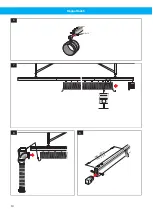
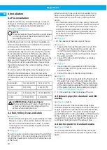
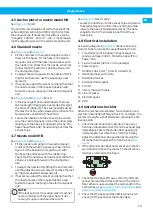
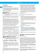
Before MagnaTrack S can be installed, a suitable po-
sition must be determined in relation to the vehicle’s
parking space in the station.
The distance from the floor to the bottom edge of the
rail should normally be 3–5 m (10–16 ft). The rail is to
be installed at least 0.3 m (1 ft) from walls, pillars etc.
The distance from the rail’s leading edge to the sta-
tion door should be as short as possible. Make sure the
door can open freely without interference to the rail.
If MagnaTrack S is to be used between two vehicles,
the distance between the vehicles must be at least
0.6 m (24 in).
The entire system should be protected against rain.
When the horizontal hose is fully compressed, its
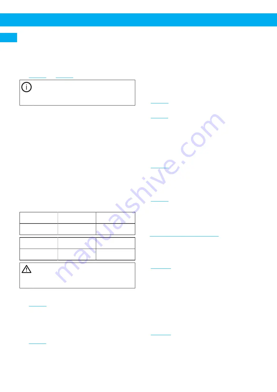
length is approximatelly 16 % of the rail's total length.
The distance A must not be less than shown in the
table.
Rail length
5.9 m (19.4 ft)
7.0 m (23.1 ft)
A min.
0 m (0 ft)
0.2 m (0.7 ft)
Rail length
9.5 m (31.2 ft)
11.8 m (38.7 ft)
A min.
0.5 m (1.5 ft)
0.9 m (3 ft)
WARNING! Risk of personal injury
When mounting MagnaTrack S, check that the
system will not snag protruding parts on the
vehicle when driving in or out.
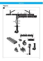
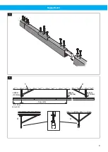
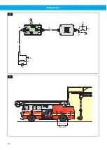
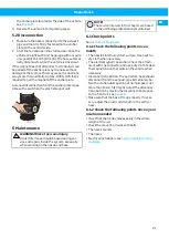
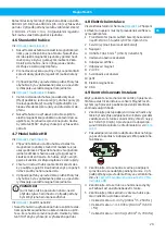
4.2 Rail, trolley, hose and cable
See
• Fasten the mounting chains, approximately 2,4 m (8
ft) apart, in every other profile. Place all the rail pro-
files in line with each other on the floor, as shown
in the figure. Screw the profiles together with the
lengthening joints.
See
The entire guide rail can be mounted with a slight fall:
50 - 100 mm (2 - 4 in) is recommended per 6 m (20 ft)
length (the lowest point to be at the station door end
of the track).
When mounting the rail, ensure that suitable fixing
bolts are used considering the ceiling construction
material and the traction forces in the suspension
points.
• Lift the whole rail and fit it in the ceiling. The mount-
ing devices are to be fixed in bars, brackets or similar
arrangements according to the examples. The first
and the last mounting bracket should be braced,
see items 1 and 2. All mounting brackets are to be
braced with bracing bars positioned sideways ac-
cording to item 3 or 4.
• Fit the adaptor at the back edge of the rail.
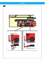
1
Suspend the hose by threading the carriers into
the guide track. Make sure the carriers are cor-
rectly fitted according to the figure. Also check
that they are free running so they do not snag in
the guide rail joints.
2
Connect the cable to a transformer, secondary
voltage 24 V AC.
.
1
Use suitable lifting equipment to lift the trolley.
Roll the trolley in to the guide track. Connect the
horizontal hose.
2
Connect the cable to the disconnection box.
1
Fit the disconnection magnet on the front part of
the guide track and on the same side as the dis-
connection box on the trolley. The exact distance
of the disconnection magnet from the front edge
of the guide track must be checked according to
Section 4.9 Installation checklist
2
Fit the end stop in the front edge of the rail.
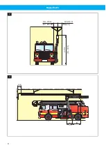
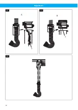
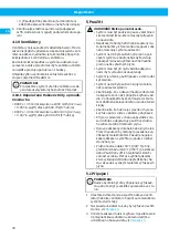
4.3 Exhaust pipe (for standard- and HB-
nozzle)
item A.
For the best results, side mounted exhaust pipes
should be positioned according to the figure and point
at right angles to the coachwork or a little backwards,
yet not more than 45°. The pipe should be straight
and lie flush with or protrude slightly out from the side
of the vehicle. It is possible that modifications may be
required to the exhaust system of the vehicle to en-
sure the optimum position of the exhaust pipe.
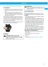
4.4 Anchor plate for standard nozzle
item A.
The anchor plate should be fitted to the side of the
vehicle according to the measurements given in the
figure.
18
Summary of Contents for MagnaTrack S
Page 8: ...MagnaTrack S 0 3 0 5 m min 0 3 m 3 5 m 12 20 in 12 in 10 16 ft 2 1 0 m 3 ft A 0 3 m 12 in 3 8...
Page 10: ...MagnaTrack S M8 x 12 6 7 8 m min 0 8 m in 2 5 ft 9 10...
Page 12: ...MagnaTrack S 1 A 11 1 B 12 13 12...
Page 13: ...MagnaTrack S 1 2 2 14 A B1 B2 15 13...
Page 14: ...MagnaTrack S PE 2 3 4 5 6 7 8 9 10 12 11 1 16 max 1 m max 3 ft 17 14...
Page 95: ...www nederman com...


