background image

MagnaTrack ST

EN

12

Preface

This manual is for the correct installation, use and maintenance of this product. 

Read it carefully before using this product or carrying out maintenance. 

Replace the manual immediately if lost.
This product has been designed to meet the requirements of relevant EC 

directives. To maintain this status, all installation, repair and maintenance 

work for this product is to be carried out by qualified personnel using only 

original spare parts. Contact the nearest authorized distributor or Nederman for 

advice on technical service and obtaining spare  parts. 

Nederman continuously improves its products’ design and efficiency through 

modifications, and reserves the right to do so without introducing these 

improvements to previously supplied products. Nederman also reserve the right 

to, without previous notice, modify data and  equipment as well as operating 

and maintenance instructions.

Notices

This document contains important information that is presented either as a 

warning, caution or note. See the following examples:

WARNING! 

Type of injury.

Warnings indicate a potential hazard to the health and safety of personnel, and 

how that hazard may be avoided. 

CAUTION! Type of risk. 

Cautions indicate a potential hazard to the product but not to personnel, and 

how that hazard may be avoided.

NOTE! 

Notes contain other information that is important for personnel.

Description

3.1 

Technical data

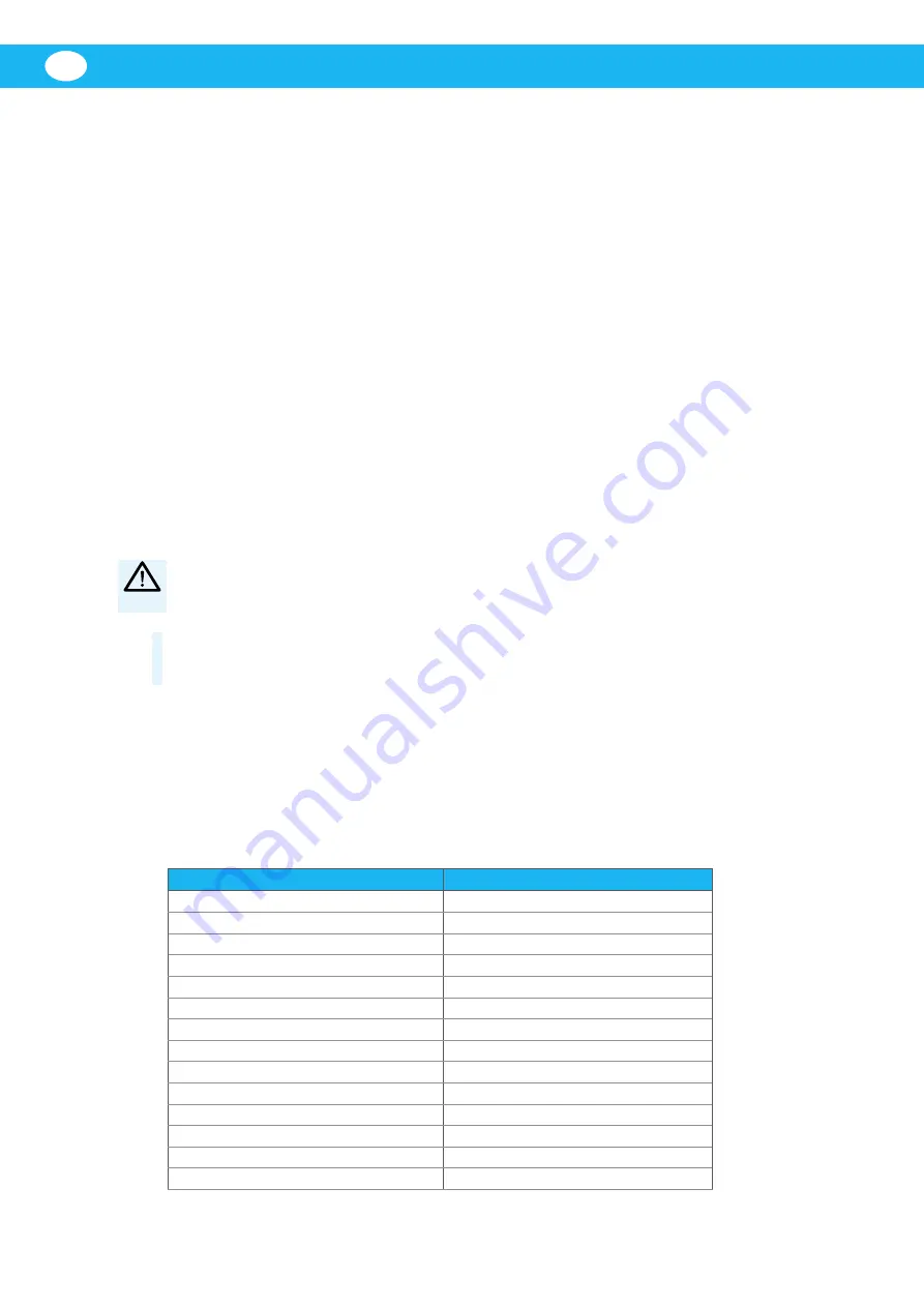
Table 3-1: Technical data

MagnaTrack ST

Mounting height

3–4 m (10–13 ft)

User speed

10 km/h (6.3 mph)

Airflow, engine size 0–4 litres

400 m

3

/h (250 cfm)

Airflow, engine size 4–10 litres

1000 m

3

/h (600 cfm)

Pressure drop at 400 m

3

/h (250 cfm)

300 Pa (1.2 in wg)

Pressure drop at 1000 m

3

/h (600 cfm)

1550 Pa (6.2 in wg)

Hosediameter

125 mm (5")

Material, hose (overrunnable)

EPDM/PP coated fabric (thermoplastic)

Material, rail

aluminium

Temperature resistance, hose

150 

°

C (300 

°

F)

Transformer, secundary voltage

26 V DC

Transformer, power consumption

0.1 A

Transformer, capacity

5 VA

Power supply

230 V AC, 1~ or 115 V AC, 1~

Summary of Contents for MagnaTrack ST

Page 1: ...al instruction manual EN INSTRUCTION MANUAL Translation of original instruction manual CS NÁVOD K OBSLUZE DE BEDIENUNGSANLEITUNG ES MANUAL DE INSTRUCCIONES FR MANUEL D INSTRUCTION NL HANDLEIDING PL INSTRUKCJA UŻYTKOWANIA SV ANVÄNDARMANUAL Instruction manual ...

Page 2: ...MagnaTrack ST 2 ...

Page 3: ...MagnaTrack ST 3 Declaration of conformity 4 Figures 6 English 11 Český 19 Deutch 27 Español 35 Français 43 Nederlands 51 Polski 59 Svenska 67 ...

Page 4: ...011 class B El director técnico es responsable de la documentación técnica Español ES Deklaracja zgodności My AB Ph Nederman Co niniejszym oświadczamy na naszą własną odpowiedzialność że produkty MagnaTrack ST firmy Nederman wraz z akcesoriami których dotyczy niniejsza deklaracja są zgodne z następującymi przepisami Dyrektywy 2006 42 EC 2006 95 EC 2004 108 EC Normy EN ISO 12100 1 2 EN 61000 6 4 EN...

Page 5: ...MagnaTrack ST 5 ...

Page 6: ...MagnaTrack ST 6 Figures 0 3 0 5 m 1 ft 1 ft 8 in min 0 3 m 3 4 m 10 13 ft min 1 ft X 1300 N 1300 N 1300 N 2 4 m 8 ft 1 ft 8 in 2 ft 0 5 0 6 m 1300 N 1300 N 1300 N 1 3 4 2 2 1 3 4 ...

Page 7: ...MagnaTrack ST 7 1 2 3 4 min 0 8 m 2 ft 8 in 6 5 8 7 ...

Page 8: ...7 8 N L PE N L 3 Secondary voltage 26 V DC Power consumption 0 1 A Capacity 5 VA Protection class IP 54 5 1 r o 1 C A V 0 3 2 1 C A V 5 1 1 e l b a c n o i t c e n n o C m m 5 1 G 3 F N R 5 0 H 2 6 6 230 V Europe standard Block 3 4 connected at delivery 115 V US Canada standard Block 2 4 and 3 5 2 4 Connections should be carried out by electrician 7 24 V DC VDR 8 Wiring diagram 10 9 11 12 ...

Page 9: ...MagnaTrack ST 9 1 m 3 ft switch 13 14 15 ...

Page 10: ...MagnaTrack ST 10 1 2 20 29 22 13 15 12 9 14 25 16 2 1 3 18 27 30 5 16 17 ...

Page 11: ... 13 4 1 Mounting instruction 13 4 1 1 The exhaust pipe 14 4 1 2 Anchor plate 14 4 1 3 Nozzle 14 4 1 4 Electrical installation 14 4 1 5 Installation checklist 14 4 1 6 Fans 15 4 1 7 Connection 15 4 1 8 Disconnection 15 5 Maintenance 16 5 1 Check these points when needed 16 5 2 Balancer 16 6 Maintenance 17 6 1 Spare parts 17 7 Recycling 17 Figures 6 Table of contents ...

Page 12: ...tructions 2 Notices This document contains important information that is presented either as a warning caution or note See the following examples WARNING Type of injury Warnings indicate a potential hazard to the health and safety of personnel and how that hazard may be avoided CAUTION Type of risk Cautions indicate a potential hazard to the product but not to personnel and how that hazard may be ...

Page 13: ...r out 3 See Figure 4 Lift the whole rail and fit it in the ceiling The mounting devices is to be fixed in bars brackets or similar arrangements according to the examples The first and the last mounting bracket should be braced see Figure 4 item 1 and 2 All mounting brackets is to be braced with bracing bars positioned sideways according to one of item 3 and 4 in Figure 4 When mounting the rail ens...

Page 14: ...d in the driving direction Adjusting screw see Figure 10 item X When the anchor plate has been fixed in its correct position it is possible to adjust the nozzle by loosening the adjusting screw and moving the leaf spring some upwards or downwards Locate the nozzle on to the exhaust pipe and secure the electro magnetic unit on the anchor plate making sure the hose is tensioned correctly with a 90 b...

Page 15: ...ction 1 Open the station door and start the exhaust extraction fan 2 Reverse the vehicle in so that the exhaust pipe is just at the station door see Figure 13 3 Locate the nozzle of the flexible hose on the exhaust pipe Fasten the electromagnetic unit onto the anchor plate located on the side of the vehicle see Figure 14 and Figure 11 Alt 1 and Alt 2 4 Reverse the vehicle into its parking space Th...

Page 16: ...rail 5 Check the mounting devices with bolts 6 The cord on the balancer 7 The hoses 8 The nozzle s internal contact surface Clean with a dry cloyh when necessary 5 2 Balancer Increasing Spring Tension 1 Turn the mainshaft 1 with a wrench in a counter clockwise direction Turn mainshaft 1 4 turn 1 click at a time until desired tension is achieved see Figure 16 Decreasing Spring Tension 1 Turn mainsh...

Page 17: ... with parts or materials from the suction system Repair of damaged cables or other electrical components should be done by a qualified electrician If the power cable failed please replace only with the same type 6 Maintenance Installation repair and maintenance work is to be carried out by qualified personnel using only original Nederman spare parts Contact your nearest authorized distributor or N...

Page 18: ...MagnaTrack ST EN 18 ...

Page 19: ...4 1 Montážní pokyny 21 4 1 1 Výfuková trubka 22 4 1 2 Kotevní destička 22 4 1 3 Hubice 22 4 1 4 Elektrická instalace 22 4 1 5 Kontrolní seznam instalace 22 4 1 6 Ventilátory 23 4 1 7 Připojení 23 4 1 8 Odpojení 23 5 Údržba 24 5 1 V případě potřeby zkontrolujte tato místa 24 5 2 Vyvažovač 24 6 Údržba 25 6 1 Náhradní díly 25 7 Recyklace 25 Obrázky 6 Obsah ...

Page 20: ...ozní a servisní pokyny 2 Poznámky Tento dokument obsahuje důležité informace které jsou prezentovány jako upozornění varování nebo sdělení Viz následující příklady VAROVÁNÍ Typ poranění Varování upozorňují na možné riziko ohrožující zdraví a bezpečnost osob a na způsob jak se lze těchto rizik vyvarovat POZOR Typ rizika Upozornění informují o možném riziku které ohrožuje zdraví a bezpečnost osob a ...

Page 21: ...ění 3 Viz obrázek 4 Zvedněte celou kolejnici a připevněte ji ke stropu Kotevní konstrukci je vhodné zavětrovat či jinak zpevnit podle příkladů První a poslední montážní konzole musí být podepřeny viz obrázek 4 bod 1 a 2 Všechny montážní konzole musí být podepřeny výztužnými tyčemi umístěnými po straně podle bodů 3 a 4 na obrázku 4 Při montáži kolejnice se ujistěte že jsou použity vhodné připevňova...

Page 22: ...ízdy Stavěcí šroub viz obrázek 10 bod X Když je kotevní destička uchycena ve správné poloze je možné seřídit hubici uvolněním stavěcího šroubu a posunutím listové pružiny nahoru nebo dolů Umístěte hubici na výfuk a zajistěte elektromagnetickou jednotku na kotevní destičku a ujistěte se že hadice je správně napnuta s 90 ohybem k výfuku viz možnost 1 a možnost 2 na obrázku 11 4 1 4 Elektrická instal...

Page 23: ... elektrický systém včetně ventilátoru se doporučuje uzamykatelný bezpečnostní spínač 4 1 7 Připojení 1 Otevřete dveře stanice a spusťte odsávací ventilátor 2 Nacouvejte vozidlem tak aby byl výfuk ve dveřích stanice viz obrázek 13 3 Umístěte odsávací hubici k výfuku Upevněte elektromagnetickou jednotku na kotevní destičku umístěnou na boku vozidla viz obrázek 14 a obrázek 11 možnosti 1 a 2 4 Nacouv...

Page 24: ...jte pevnost ukotvení celého systému 6 Provaz vyvažovače 7 Trubice 8 Vnitřní kontaktní povrch hubice Očistěte v případě potřeby suchým hadříkem 5 2 Vyvažovač Zvýšení napnutí pružiny 1 Otočte hlavní hřídel 1 klíčem ve směru proti chodu hodin Otočte hlavní hřídelí o 1 4 otáčky 1 cvaknutí najednou dokud není dosaženo správného napnutí viz obrázek 16 Snížení napnutí pružiny 1 Otočte hlavní hřídelí 1 kl...

Page 25: ...prava poškozených kabelů nebo jiných elektrických součástí by měla být provedena kvalifikovaným elektrikářem Pokud je napájecí kabel poškozen vyměňte jej pouze za kabel stejného typu 6 Údržba Je třeba aby byla instalace opravy i údržby prováděna kvalifikovanými pracovníky za použití originálních náhradních dílů společnosti Nederman Kontaktujte vašeho nejbližšího autorizovaného distributora nebo sp...

Page 26: ...MagnaTrack ST CS 26 ...

Page 27: ... 1 Montageanleitung 29 4 1 1 Auspuff 30 4 1 2 Ankerplatte 30 4 1 3 Mundstück 30 4 1 4 Elektroinstallation 31 4 1 5 Installationskontrolle 31 4 1 6 Ventilatoren 31 4 1 7 Ankuppeln 32 4 1 8 Abkuppeln des Schlauchs 32 5 Instandhaltungsanleitung 32 5 1 Folgende Punkte bei Bedarf kontrollieren 32 5 2 Federmechanismus 33 5 3 Ersatzteile 34 6 Recycling 34 Abbildungen 6 Inhaltsverzeichnis ...

Page 28: ...ichtung entsprechende Änderungen auch an bereits gelieferten Produkten durchzuführen Wir behalten uns zudem das Recht vor Daten und Ausrüstung wie auch Bedienungs und Wartungsanleitungen ohne vorherige Ankündigung zu ändern 2 Gefahrenhinweise Die vorliegenden Unterlagen enthalten Gefahrenhinweise die von jedem Benutzer gelesen werden müssen Die Gefahrenhinweise werden in Form von Warnungen und Hin...

Page 29: ...erden siehe Abbildung 1 Der Abstand zwischen Unterkante Laufschiene und Hallenboden sollte zwischen 3 und 4 Metern betragen Seitlich sollte die Laufschiene mindestens 0 3 m Abstand zur Toröffnung haben Soll der Schlauch zwischen zwei Fahrzeugen eingesetzt werden sollten die Fahrzeuge mindestens 1 2 m voneinander entfernt stehen Der Abstand von der Vorderseite der Schiene bis zum Garagentor sollte ...

Page 30: ...Oberseite der Schiene anbringen siehe Abbildung 9 Artikel 2 9 Stoßdämpfer an der vorderen Seite der Schiene anschrauben siehe Abbildung 9 Artikel 3 10 Schraube durch das hintere Ende der Schiene durchstecken und mit Mutter sichern siehe Abbildung 9 Artikel 4 4 1 1 Auspuff Siehe Abbildung 9 Das Rohr sollte gerade sein und mit der Fahrzeugkarosserie abschließen oder seitlich geringfügig hervorstehen...

Page 31: ...stallationsarbeit kann die Absauganlage nach Überprüfung folgender Punkte in Betrieb genommen werden 1 Elektroinstallation Transformator Mikroschalter Magnet gemäß Schaltplan überprüfen 2 Luftstrom 400 1000 m3 h in der Mundstück öffnung mit Luftstrommesser kontrollieren Rotations richtung des Ventilators und oder Klappenfunktion überprüfen 3 Abkuppeln des Schlauches kontrollieren Der Abgasschlauch...

Page 32: ...nd Hallentor öffnen Fahrzeug gerade aus der Halle fahren Max Geschwindigkeit 10 km h Der Schlauch wird automatisch abgekuppelt wenn das Fahrzeug die Halle verläßt Sollte der Magnet einmal nicht automatisch ablösen wird er durch die Zugkraft des Schlauches von der Ankerplatte getrennt Dabei kann die Schlaucheinheit weiter pendeln als normal Die erforderliche Abzugskraft für den Magneten liegt je na...

Page 33: ...gsarm 2 bewegt werden kann siehe Abbildung 16 2 Verriegelungsarm 2 runterdrücken 3 Hauptachse leicht im Uhrzeigersinn drehen lassen Dabei den Verriegelungsarm loslassen und Haup tachse 1 4 Umdrehungen eine Stufe im Uhrzeiger sinn drehen lassen 4 Die Prozedur wiederholen bis die gewünschte Federspannung erreicht worden ist 5 Wenn die Federkraft erhöht wurde muß überprüft werden ob das Seil weit gen...

Page 34: ...fe die miteinander oder mit den Werkstoffen der Absauganlage reagieren können Bei Schaden an Kabel elektrischen Komponenten sollte die Reparaturarbeit von einem Fach mann ausgeführt werden Die Netzanschluss leitung darf nur durch den in der Anschluss schema beschreibenen Typ ersetzt werden 5 3 Ersatzteile Kontaktieren Sie Ihren autorisierten Händler oder AB Ph Nederman Co zur technischen Beratung ...

Page 35: ...ción de montaje 37 4 1 1 Tubo de escape 38 4 1 2 Placa de anclaje 38 4 1 3 Tobera 38 4 1 4 Instalación eléctrica 39 4 1 5 Control de instalación 39 4 1 6 Ventiladores 39 4 1 7 Activación 40 4 1 8 Desconexión 40 5 Instrucciones de cuidad 40 5 1 Controle los siguientes puntos en caso de necesidad 40 5 2 Bloque equilibrador 41 5 3 Piezas de repuesto 42 6 Reciclaje 42 Figures 6 Tabla de contenidos ...

Page 36: ...sin introducir estas mejoras en productos previamente suministrados También reservamos el derecho sin previo aviso a modificar los datos y el equipo así como las instrucciones de funcionamiento y mantenimiento 2 Avisos de peligro Este documento incluye información en materia de peligros que todos los usuarios deben leer La información de los peligros se presenta como una advertencia precaución o n...

Page 37: ...ecidir la altura y posición en relación a la posición del vehículo en el local ver la figura 1 La altura de montaje desde el piso hasta el borde inferior de la guía debe ser de 3 a 4 m La guía se debe montar a un mínimo de 0 3 m de uno de los lados de la abertura de la puerta Si el extractor se piensa utilizar entre dos vehículos la distancia entre éstos no debe ser inferior a 1 2 m La distancia e...

Page 38: ...igura 8 punto 4 4 1 1 Tubo de escape Ver la figura 9 La punta del tubo debe ser recta y quedar en línea con o sobresalir algo de la carrocería El tubo debe estar colocado de manera que la distancia hasta el borde inferior de la carro cería y hasta el cuerpo trasero de la rueda no sea inferior a la indicada en la figura Puede ser necesario modificar la posición del tubo de escape 4 1 2 Placa de anc...

Page 39: ...desconexión La manguera de succión se debe desconectar del tubo de escape inmediatamente antes de que la puerta se abra velo cidad máxima 10 km h Regule el modo de desco nexión corriendo el micro interruptor por la parte delantera de la guía ver la figura 8 punto 1 4 Compruebe que la manguera se pliegue correcta mente después de desconectarse y que no se arrastre por el suelo Si es necesario regul...

Page 40: ...ico se puede desconectar manualmente de la placa de anclaje ver la figura 15 NOTA Las mangueras soportan una temperatura constante de hasta 150 C A temperaturas más altas se puede acortar la vida útil de las mangu eras Evite trabajos con el motor en marcha que eleven la temperatura de los gases 5 Instrucciones de cuidad 5 1 Controle los siguientes puntos en caso de necesidad 1 La función magnética...

Page 41: ...Hay riesgo de daños personales Por razones de seguridad el resorte está incorporado al tambor Nuncaintentar pues quitar el resorte del tambor ADVERTENCIA Riesgo de accidentes personales y o del producto El sistema no debe ser utilizado para otros fines que succionar gases El sistema sólo se puede utilizar con la placa de anclaje magnético que debe estar montada en el vehículo El sistema no se debe...

Page 42: ...itud de piezas de repuesto Al solicitar piezas de repuesto indique siempre lo siguiente Número de la pieza y de control véase la placa de identificación del producto Indique el número y el nombre de la pieza de repuesto visite www nederman com Cantidad de piezas de recambio requeridas 6 Reciclaje El producto se ha diseñado de modo que se puedan reciclar los materiales de los componentes Sus divers...

Page 43: ... Instructions de montage 45 4 1 1 Pot d échappement 46 4 1 2 Support magnétique 46 4 1 3 Embout 46 4 1 4 Installation électrique 46 4 1 5 Contrôle de montage 47 4 1 6 Ventilateurs 47 4 1 7 Connexion 47 4 1 8 Déconnexion 48 5 Instructions d entretien 48 5 1 Contrôler les points suivants en cas de besoin 48 5 2 L équilibreur 48 5 3 Pièces de rechange 50 6 Recyclage 50 Schémas 6 Table des matières ...

Page 44: ...ns également le droit de modifier sans avis préalable les caractéristiques et les équipements ainsi que les instructions d utilisation et de maintenance 2 Mises en garde Tous les utilisateurs doivent lire les informations contenues dans le présent document au sujet des dangers Les informations relatives aux dangers sont signalées par les indications Avertissement Attention ou Remarque selon les cr...

Page 45: ...de l un des côtés de l ouverture de porte Si l extracteur est utilisé entre deux véhicules la distance entre les deux véhicules devra être d au moins 1 2 m La distance entre le bord avant du rail et la porte du garage devra être au moins 0 3 m Vérifier que la porte peut s ouvrir sans accrocher la suspension du rail Toute installation doit être protégée contre les intempéries 1 Aligner tous les pro...

Page 46: ...t d échappement devra être modifiée 4 1 2 Support magnétique Voir schéma 9 Le support magnétique doit être fixé sur le côté du véhicule 600 mm au dessus du pot d échappement Si nécessaire cette distance peut être modifiée 100 mm 25 mm en desserant la vis de réglage voir schéma 10 point X 4 1 3 Embout Fixer le ressort hélocoïdal de l embout dans le manchon magnétique avec la vis de réglage comme in...

Page 47: ...u véhicule ni à la porte du garage 4 1 6 Ventilateurs Les ventilateurs ne font pas partie de la livraison de base Chaque rail peut être branché sur un ventilateur central ou sur un ventilateur spécialement destiné à l installation Pour obtenir le meilleur résultat il est conseillé d utiliser un ventilateur par unité d extraction Pour conserver une souspression dans le système et donc éviter des fu...

Page 48: ...Instructions d entretien 5 1 Contrôler les points suivants en cas de besoin 1 Aimant Vérifier la fixation le manchon et nettoyer l aimant et le support magnétique sur le véhicule si nécessaire Utiliser un chiffon sec pour nettoyer l aimant et le support magnétique du véhicule si nécessaire 2 Déconnexion Le tuyau extrateur devra se décon necter du pot d échappement avant l ouverture de la porte vit...

Page 49: ...jamais essayer de le retirer AVERTISSEMENT Risque de blessures corporelles et de dommages à l équipement L utilisation du système est strictement réservée à l extraction de gaz d échappement Le système ne peut être utilisé qu avec le support magnétique monté sur le côté du véhicule Le système ne doit pas être utilisé en cas d inter vention sur le système d alimentation en carburant du véhicule et ...

Page 50: ...de pièces de rechange Au moment de réaliser la commande de pièces de rechange toujours indiquer ce qui suit Numéro de pièce et de contrôle cf la plaque signalétique du produit Numéro et nom détaillés de la pièce de rechange consulter www nederman com Quantité de pièces nécessaires 6 Recyclage Le produit a été conçu pour que les matériaux des composants soient recyclés Les différents types de matér...

Page 51: ...ntagehandleiding 53 4 1 1 De uitlaatpijp 54 4 1 2 Ankerplaat 54 4 1 3 Mondstuk 54 4 1 4 Elektrische installatie 54 4 1 5 Installatiecontrolelijst 55 4 1 6 Keuze van de ventilator 55 4 1 7 Aankoppeling 55 4 1 8 Ontkoppeling 56 5 Onderhoudsinstructies 56 5 1 Controleer de volgende punten wanneer nodig 56 5 2 Stabilisator 57 5 3 Reserveonderdelen 58 6 Recycling 58 Afbeeldingen 6 Inhoudsopgave ...

Page 52: ...fgaande kennisgeving gegevens en uitrusting te wijzigen evenals het wijzigen van bedienings en onderhoudsinstructies 2 Risico aanduidingen Dit document bevat informatie over risico s en alle gebruikers dienen deze informatie te lezen De informatie over risico s wordt op de volgende manier voorgesteld als een waarschuwing aanmaning of opmerking WAARSCHUWING Type letsel Waarschuwingen wijzen op een ...

Page 53: ...rail tot de deur opening moet op minstens 0 3 m zijn De deur moet wel probleemloos opengaan zonder dat ze de rail hindert Het complete systeem dient beschermd te worden tegen regen 1 Leg alle railprofielen op één lijn achter elkaar op de vloer Schroef de profielen met de verbindingsplaten aan elkaar zie afbeelding 2 2 Bevestig de montagehulpmiddelen in het midden van elk tweede profiel zie afbeeld...

Page 54: ...tlaatpijp 4 1 2 Ankerplaat Zie afbeelding 1 De ankerplaat moet worden bevestigd op de zijkant van het voertuig op 600 mm afstand van de uitlaatpijp Deze afstand kan zo nodig worden aangepast 100 mm 25 mm door de stelschroef in de elektromagnetische eenheid los te draaien zie afbeelding 8 item X 4 1 3 Mondstuk Bevestig de bladveer van het mondstuk op de elektro magnetische eenheid met de stelschroe...

Page 55: ... de microschakelaar op de voorkant van de rail te verplaatsen zie afbeelding 8 item 1 4 Controleer of de slang goed wordt opgetrokken na het ontkoppelen en of ze de garagevloer niet raakt Pas zo nodig het hefvermogen van de stabilisator aan zie afbeelding 16 5 Controleer of de slang en het mondstuk niet vasthaakt aan een deel van het voertuig of aan de garagedeur 4 1 6 Keuze van de ventilator Vent...

Page 56: ...peling van de ankerplaat is mogelijk met een schakelaar op de elektromagne tische eenheid zie afbeelding 15 LET OP De flexibele slang is bestand tegen een temperatuur van 150 C Hogere temperaturen zullen de levensduur van de slang aanzienlijk verkorten Vermijd daarom lange periodes van continu bedrijf waarbij hoge temperaturen worden opgewekt 5 Onderhoudsinstructies 5 1 Controleer de volgende punt...

Page 57: ...Risico op letsel Verwijder de veer nooit uit de trommel of het veerpakket Vervangingsveren zijn voor de veiligheid gesealed WAARSCHUWING Risico op letsels en of beschadiging van het systeem Het systeem mag niet worden gebruikt voor andere doeleinden dan het afzuigen van uitlaatgassen Het systeem mag alleen worden gebruikt in combinatie met de ankerplaat die op het voertuig gemonteerd moet zijn Het...

Page 58: ...u reserveonderdelen bestelt dient u steeds het volgende te vermelden Onderdeel en controlenummer raadpleeg het productidentificatieplaatje Detailnummer en naam van het reserveonderdeel zie www nederman com Het gewenste aantal onderdelen 6 Recycling Het product werd zodanig ontworpen dat de materialen van de onderdelen gerecycled kunnen worden De verschillende materiaaltypes moeten overeenkomstig d...

Page 59: ...kcje dotyczące montażu 61 4 1 1 Rura wydechowa 62 4 1 2 Płyta kotwiąca 62 4 1 3 Ssawka 62 4 1 4 Instalacja elektryczna 62 4 1 5 Lista kontrolna instalacji 63 4 1 6 Wentylatory 63 4 1 7 Podłączanie 63 4 1 8 Odłączanie 64 5 Konserwacja 64 5 1 Kwestie wymagające sprawdzenia w razie potrzeby 64 5 2 Balanser 65 6 Konserwacja 66 6 1 Części zamienne 66 7 Recykling 66 Rysunki 6 Spis treści ...

Page 60: ...niej produktach Firma Nederman zastrzega sobie również prawo do modyfikowania danych i urządzeń oraz instrukcji dotyczących obsługi i konserwacji bez uprzedniego powiadomienia 2 Ostrzeżenia Niniejszy dokument zawiera ważne informacje przedstawione w postaci ostrzeżeń przestróg lub uwag Oto ich przykłady OSTRZEŻENIE Typ obrażeń ciała Ostrzeżenie wskazuje na potencjalne zagrożenie dla zdrowia i bezp...

Page 61: ... Skręć ze sobą profile szyny używając łączników patrz rysunek 2 2 Wzmocnij podwieszenie szyny pośrodku każdego z profilów patrz rysunek 3 OSTRZEŻENIE Ryzyko odniesienia obrażeń ciała Podczas montażu MagnaTrack Basic należy zapewnić że system nie będzie zahaczał o wystające części pojazdu podczas wjeżdżania i wyjeżdżania 3 Patrz rysunek 4 Unieś całą szynę i przymocuj ją do stropu Podwieszenie szyny...

Page 62: ...o 25 mm 1 cal luzując śrubę regulacyjną elektromagnesu patrz rysunek 10 pozycja X 4 1 3 Ssawka Przymocuj sprężynę ssawki do elektromagnesu z wykorzystaniem śruby regulacyjnej tak jak przedstawiono to na rysunku 10 pozycja X Zamocuj wąż w zespole magnetycznym za pomocą opaski zaciskowej i zabezpiecz je opaską gumową Sprawdź czy ssawka niepodłączona do pojazdu jest skierowana do przodu w kierunku ja...

Page 63: ... 16 5 Upewnij się że wąż i ssawka nie dotykają w żadnym miejscu pojazdu lub bramy garażu 4 1 6 Wentylatory Wentylatory nie wchodzą w skład podstawowego zestawu W celu uzyskiwania najlepszych wyników zaleca się stosowanie jednego wentylatora na szynę odciągową Możliwe jest również podłączenie kilku szyn do wentylatora centralnego W celu uzyskania podciśnienia w instalacji kanałowej i zapobieżenia w...

Page 64: ...peratur spalin 5 Konserwacja Wszystkie prace związane z instalacją naprawami i konserwacją muszą być wykonywane przez wykwalifikowany personel Aby uzyskać poradę w kwestii serwisu technicznego lub pomoc w sprawie części zamiennych skontaktuj się z firmą Nederman lub jej najbliższym autoryzowanym dystrybutorem UWAGA Częstotliwość serwisowania podana w niniejszym rozdziale odnosi się do profesjonaln...

Page 65: ...odpierającego i zwolnienia wszelkiego napięcia sprężyny OSTRZEŻENIE Ryzyko odniesienia obrażeń ciała Nie wolno wyjmować sprężyny z zespołu bębna Dla bezpieczeństwa sprężyny zamienne są uszczelnione OSTRZEŻENIE Ryzyko odniesienia obrażeń ciała Systemu nie wolno używać do celów innych niż odciąganie spalin Systemu należy używać wyłącznie w połączeniu z płytą kotwiącą przeznaczoną do zamontowania na ...

Page 66: ...sprawie części zamiennych skontaktuj się z firmą Nederman lub jej najbliższym autoryzowanym dystrybutorem Patrz również www nederman com Zamawianie części zamiennych Zamawiając części zamienne zawsze podawaj następujące informacje numer części i numer kontrolny patrz tabliczka znamionowa produktu numer i nazwę części zamiennej patrz www nederman com liczbę wymaganych części 7 Recykling Produkt zos...

Page 67: ...69 4 1 Montageinstruktion 69 4 1 1 Avgasröret 70 4 1 2 Ankarplattan 70 4 1 3 Munstycke 70 4 1 4 Elektrisk installation 70 4 1 5 Installationskontroll 70 4 1 6 Fläktar 71 4 1 7 Tillkoppling 71 4 1 8 Avkoppling 71 5 Skötselinstruktion 72 5 1 Kontrollera följande punkter vid behov 72 5 2 Balansblock 72 5 3 Reservdelar 73 6 Återvinning 73 Figurer 6 Innehållsförteckning ...

Page 68: ...h underhållsinstruktioner 2 Riskmeddelanden Det här dokumentet innehåller riskinformation som måste läsas igenom av samtliga användare Riskinformationen presenteras som en varning ett försiktighetsmeddelande eller en kommentar på följande sätt VARNING Typ av skada Varningar anger en möjlig risk för användarens hälsa och säkerhet De anger tydligt vilken typ av fara det rör sig om och hur den ska un...

Page 69: ...VARNING Risk för personskador Vid montage av skenan kontrollera att slangen inte kan hänga upp sig i några utstickande detaljer på fordonet vid ut eller inkörning 3 Se figur 4 Häng upp hela skenan och montera fast den i taket Upphängningsdonen skruvas fast i konsoler takbalkar eller liknande enligt bildexemplen Första och sista upphängningspunkten ska stagas upp se figur 4 punkt 1 och 2 Samtliga u...

Page 70: ... finns möjligheten att justera munstycket genom att lossa justerskruven och föra bladfjädern något uppåt eller nedåt Placera munstycket över avgasröret och fäst magnetstosen på ankarplattan och se till att slangen spännes på rätt sätt Slangen skall bilda ca 90 vinkel mot avgasröret se Alt 1 och Alt 2 i figur 11 4 1 4 Elektrisk installation Se kopplingsscema figur 12 Anslutning till nätet från tran...

Page 71: ...ppling 1 Öppna garageporten och starta fläkten för avgasutsugning 2 Backa in fordonet så pass långt att avgasröret befinner sig vid garageporten se figur 13 3 Trä slangens munstycke på avgasröret Fäst sedan slangen mot magnetankaret som skall sitta fast på fordonets sida se figur 14 4 Backa in fordonet och stanna på avsedd plats Låt alltid slangen vara ansluten till avgasröret under den tid fordon...

Page 72: ...en skiftnyckel Obs Vrid huvudaxeln endast ett kvarts varv åt gången tills önskad fjäderspänning har uppnåtts se figur 16 Minskning av fjäderkraften 1 Vrid huvudaxeln 1 moturs med en skiftnyckel precis tillräckligt för att kunna manövrera låsarmen 2 se figur 16 2 Tryck ned låsarmen 2 3 Låt huvudaxeln sakta vridas medurs och frigör låsarmen innan huvudaxeln vrides ett kvarts varv ett snäpp 4 Upprepa...

Page 73: ...r på fordonet Sug inte hett brinnande eller antänt material eller substanser som kan reagera med delar eller material från systemet Reparation av kablar elektriska komponenter ska utföras av behörig fackman Om strömkabeln skadats ersätt den enbart med samma kabeltyp 5 3 Reservdelar Kontakta närmaste auktoriserade återförsäljare eller AB Ph Nederman Co för information om teknisk service eller om du...

Page 74: ...MagnaTrack ST SV 74 ...

Page 75: ......

Page 76: ...www nederman com ...

Reviews: