


ExhaustRail Touchless
2
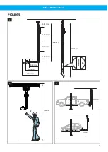
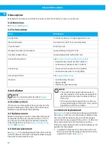
Based on the rail position calculated in step 1, de-
termine the length of the shortest vehicle that can
be used with the unit. See
.
3
If necessary, adjust the final placement of the rail
so that the maximum number of cars of different
lengths can be used with the unit.
NOTE!
For technical advice about installation, contact
Nederman.
4.5 Install rail sections and fan
For installing the rail system and connecting the trol-
ley, see the manual, Mounting instructions, rail.
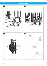
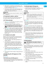
4.6 Telescopic pipe
1
. Fit the jointed arm together with the
nozzle to the telescopic pipe.
2
Screw two screws all the way in, until stop
(without using force), and then loosen half a turn.
CAUTION! Risk of equipment damage
Do not force the screws, they may break.
3
. Fit the lever according to (A) and (B).
Compress all sections of the telescopic pipe to the
stop position and fasten the screw. The support
ring above the jointed arm must rest on the top
flange of the lever in order to keep the telescopic
pipe in place.
4.7 Installation checklist
When the mechanical assembly and fan connection
of the system are complete, it is ready for use after
double-checking the following points.
1
Check the airflow in the nozzle opening with an
airflow indicator.
2
Check that there is enough suction capacity in
the extraction unit before it is connected to the
vehicle’s exhaust pipe. If not, check the fan im-
peller rotation direction and/or damper function.
If necessary check the installation of the fan start
switch.
3
Check the telescopic function. When required,
adjust the balancer lifting power. See
tion 4.8 Adjusting the lifting power of the balan-
cer
4
Check that the suction trolley can easily be moved
in the rail.
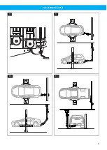
4.8 Adjusting the lifting power of the
balancer
See
.
4.8.1 Increasing the lifting power
• Hold the knurled wheel (A) of the balancer drum in a
steady grip and turn the balancer drum (B) clockwise
for increased lifting power.
4.8.2 Reducing the lifting power
1
Pull a little cord from the balancer drum.
2
Hold the balancer drum (B) in a steady grip and re-
move one or two revolutions of the cord.
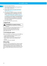
5 Using
NOTE!
• The system is designed for use only with sta-
tionary vehicles. The vehicle must not be
moved when the nozzle has been placed next
to the vehicle exhaust pipe.
• Use two hands when moving the nozzle and
arm.
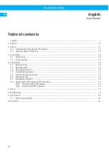
• Press down the blue button (1) on top of the nozzle.
Move the arm and nozzle into position and then re-
lease the blue button. The joints (2) are now locked
into place.
. The extraction unit is equipped with a
mechanical damper. The damper is closed when the
lever on the top section of the extraction unit is pulled
out and the telescopic unit is moved up to the parking
position (A). There is a stop (B) on the lever to prevent
unintentional from shutting off of the damper func-
tion.
1
Pull out the lever to pull down the telescopic unit.
The telescopic unit is balanced and will stay in the
position where it is left.
2
Check the positioning of the nozzle to make sure it
is properly positioned. The nozzle shall be placed a
bit behind the vehicle exhaust pipe. See
,
.
6 Maintenance
CAUTION! Risk of equipment damage
Use only N
$
e
$
d
$
e
$
r
$
m
$
a
$
n
$
original spare parts and ac-
cessories.
Check the following points, regarding fixing, function-
ing or wear, at periodic intervals but at least annually
or when replacing
parts.
1
Rail
2
Trolley stop
3
Wheels of the suction trolley.
4
Check that the suction trolley moves easily in the
whole length of the rail.
5
Check the guideway of the suction trolley regard-
ing wear. Clean the guideway if necessary.
6
Check the rubber buffer of the suction trolley.
7
Check that there are no cracks around the wheel
carriers of the suction trolley.
8
The nozzle
9
Check that there is enough suction power in the
nozzle.
EN
13


