GB
ENGLISH
DEUTSCH
D
36
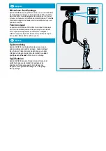
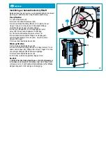
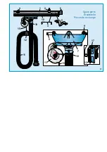
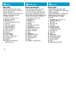
Einstellung der Rückziehkraft des Balancers
Der Balancer verfügt über eine werkseingestellte Rückziehkraft.
Die Rückziehkraft kann wie folgt eingestellt werden:
Federkraft verstärken
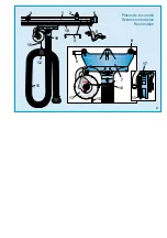
1. Seilstopp (C) lösen.
2. Sicherheitsschraube (A) lösen.
3. Einen Verriegelungsgriff (B) verwenden und im Gegenuhr-
zeigersinn jeweils eine Umdrehung drehen. Jede Umdrehung
wird durch ein deutliches Klicken gekennzeichnet. Drehen, bis
sich der Schlauch in die gewünschte Ruheposition bewegt hat.
4. Den Seilstopp (C) bis zur Einstellschraube des Anschlag-
bügels (D) schieben. Den Seilstopp in dieser Position befestigen.
5. Den Verriegelungsgriff eine weitere Umdrehung drehen.
6. Prüfen, dass der Seilstopp vom Anschlagbügel aufgefangen
wird und dass die Klappe geschlossen ist. Andernfalls die Ein-
stellschraube (D) ein wenig nach unten drehen.
7. Sicherheitsschraube (A) anbringen.
Federkraft reduzieren
1. Sicherheitsschraube (A) lösen.
2. Einen Verriegelungsgriff (B) verwenden und ein wenig im
Gegenuhrzeigersinn drehen. Knopf (E) drücken. Jeweils um
eine Umdrehung lösen. Für jede Umdrehung kehrt der Knopf
(E) in seine ursprüngliche Position zurück.
3. Sicherheitsschraube (A) anbringen.
4. Bei Bedarf die Position des Seilstopps auf dem Seil justieren.
Funktion prüfen
1. Sicherstellen, die Sicherheitsschraube (A) fest montiert ist.
2. Den Schlauch vollständig ausziehen und prüfen, dass der Ba-
lancer den Schlauch ruhig und gleichmäßig in seine normale Po-
sition bringt. Den Schlauch bei der Rückkehr mit der Hand halten.
Adjusting the lifting power of the balancer
The balancer has a factory set lifting power. It is possible to
adjust the lifting power according to the following description.
Increasing the lifting power
1. Loosen the stop ball (C)
2. Unscrew the safety screw (A).
3. Use a locking handle (B) and turn anti-clockwise one revo-
lution at a time. Each revolution is marked with a "click" posi-
tion. Turn until the hose has moved to required resting position.
4. Push the stop ball (C) up to the stop clamp adjusting
screw (D). Fasten the stop ball in this position.
5. Turn the locking handle one revolution more.
6. Check that the stop ball is catched by the stop clamp
and that the damper is closed. If not, screw the adjusting
screw (D) downwards a little.
7. Fasten the safety screw (A).
Reducing the lifting power
1. Unscrew the safety screw (A).
2. Use a lockng handle (B) and turn a little anti-clockwise. Then
push the button (E). Release one revolution at a time. For each
revolution the button (E) returns to its original position.
3. Fasten the safety screw (A).
4. If necessary, adjust the stop ball position on the cord.
Checking of procedure
1. Make sure the safety screw (A) is in position.
2. Pull the hose to its maximum extent and check that the
balancer winds the hose to its normal position at an even and
steady pace. Hold the hose by hand while it returns.
Summary of Contents for SYSTEM 920
Page 2: ...SYSTEM 920 400 for stationary vehicles ...
Page 11: ...11 0 5 1 0 m recommended H 3 4 m A 150 ...
Page 15: ...15 5 m max 5 0 m 1 EXAMPLES 7 5 m 12 5 m 15 m 10 m 17 5 m 20 m 22 5 m B A 1 25 m 2 5 m 1 25 m ...
Page 17: ...17 5 m max 5 0 m 1 EXAMPLES 7 5 m 12 5 m 15 m 10 m 17 5 m 20 m 22 5 m B A 1 25 m 2 5 m 1 25 m ...
Page 19: ...3 max 1 25 m 2 2 19 ...
Page 21: ...21 4a 4e 4d 4f TEKS ST 4 8 x 16 4b 4c max 19 mm ...
Page 23: ...23 4a 4e 4d 4f TEKS ST 4 8 x 16 4b 4c max 19 mm ...
Page 27: ...27 TEKS ST 4 8 x 16 9a 9b Ø 160 mm Ø 200 mm ...
Page 41: ...41 Safetylock lock 2 3 6 8 9 10 4 7 1 5 11 ...


