background image

13

Prior to installation, always follow the

instructions and warnings in the chapter
entitled ”Safety instructions”!

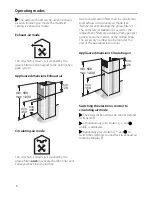
Exhaust-air mode

The exhaust air is conveyed upwards via a

ventilation shaft or directly through the outer
wall to the exterior.

NOTE: 

The exhaust air must not be conveyed

into a functioning smoke or exhaust gas flue or
into a shaft which is used to ventilate 
installation rooms which contain heating 
appliances.

Before conveying the exhaust air into a

non-functioning smoke or exhaust gas flue,
obtain the consent of the appropriate heating
engineer.

Discharge exhaust air in accordance with

the official and statutory regulations (e.g.
regional building laws).

If the exhaust air is conveyed through the

outer wall, a telescopic wall box should be
used.

To ensure optimum performance, the
extractor hood requires:

– a short, straight exhaust air pipe and
– the largest possible pipe diameter.

If pipe bends cannot be avoided, ensure

the largest possible radii. 

NOTE: 

If long, rough exhaust air pipes, a lot of

pipe bends or pipe diameters less than 
150 mm are used, the air capacity will be less
than optimum and there will be an increase in
noise.

Use only pipes or hoses made of non-

combustible material for installation of the
exhaust air duct.

The manufacturer of the extractor hoods is

not responsible for complaints which can be
attributed to planning and design of the
pipework.

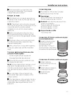
Connecting pipes

The diameter of the exhaust air pipes

should not be less than 150 mm.

Round pipes:

We recommend an inner diameter of 
150 mm, however at least 120 mm.

Flat ducts

must have the same inner cross-

section as round pipes.
There should be no sharp bends.
Ø 150 mm approx. 177 cm

2

Ø 120 mm approx. 113 cm

2

If pipe diameters differ:

Use sealing strips.

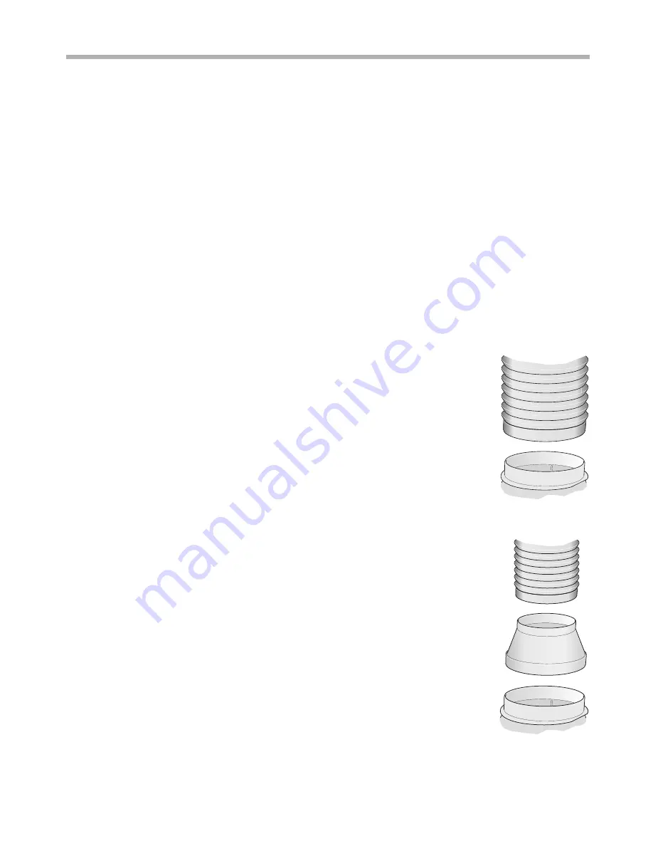
Connection of 150 mm ø exhaust air pipe
(recommended size)

Attach exhaust air pipe

directly to the air-pipe
connector and seal
appropriately. If using an
aluminium pipe, smooth the
connection area beforehand.

Connection of 120 mm ø exhaust air pipe

Attach reducing

connector directly to the air-
pipe connector.

Attach exhaust air pipe to

the reducing connector.

Seal both joints

appropriately.

Installation instructions

Summary of Contents for D72F58N0GB

Page 1: ...Installation instructions and how to use and look after your built in cooker hoods NEFF UK Ltd...

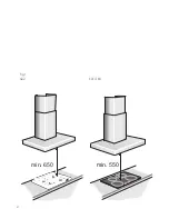
Page 2: ...Abb 1 ELECTRO Fig 1 GAZ min 650 min 550 2...

Page 3: ...installation 7 Operating modes 8 Exhaust air mode 8 Circulating air mode 8 Operation 9 Cleaning and Care 10 Removing and installing the grease filters 11 Removing and installing the metal mesh grease...

Page 4: ...rials can be reclaimed by recycling old appliances This appliance is identified according to the European Directive 2002 96 EC on waste electrical and electronic equipment WEEE The directive specifies...

Page 5: ...stomer service or a similarly qualified person to prevent hazardous situations Only a qualified technician may install including electrical connection service or repair the extractor hood Always isola...

Page 6: ...bs observe the appropriate national statutory regulations e g in Germany Technische Regeln Gasinstallation TRGI Observe the currently valid installation regulations and instructions of the gas applian...

Page 7: ...if you are cooking food with oils or fats e g chips Overheated oils or fats can easily ignite A risk of fire can be prevented by cleaning the grease filters regularly and changing the activated carbo...

Page 8: ...ust be connected and switched off Simultaneously press buttons and r until is displayed Repeatedly press buttons and r to switch the electronic control back to exhaust air mode by display The extracto...

Page 9: ...f by hand the fan automatically switches back to setting 2 after 10 minutes Fan run on Press button r The fan runs for 10 minutes at the selected setting The r symbol is lit on the display Then the fa...

Page 10: ...ase particles from the kitchen fumes The filter mats consist of fire proof metal RISK OF FIRE As the filters become more saturated with greasy residue the flammability increases The function of the ex...

Page 11: ...be replaced approximately 2x year The activated carbon filter is available from specialist outlets customer service or the Online Shop see Optional accessories Use original filters only Activated carb...

Page 12: ...ch the glass tube Therefore use a clean cloth when inserting the bulb 3 Close the inner frame of the halogen bulb NOTE The inner frame of the halogen bulb will not close unless it was fully opened bef...

Page 13: ...ong rough exhaust air pipes a lot of pipe bends or pipe diameters less than 150 mm are used the air capacity will be less than optimum and there will be an increase in noise Use only pipes or hoses ma...

Page 14: ...equired connection data can be found on the rating plate inside the appliance when the grease filters have been removed Length of the power cord approx 1 30 m This extractor hood complies with the EC...

Page 15: ...bearing capacity Ensure that the depth of the drilled holes corresponds with the length of the screws Ensure that the wall plugs are secure Max weight in kg 40 Design subject to modification in line w...

Page 16: ...Mark the holes for the safety screws Detach the extractor hood drill holes for the safety screws and press in wall plugs flush with the wall 2 Attach the extractor hood and screw in the safety screws...

Page 17: ...earing protective gloves during installation 1 Separate the flue ducts To do this remove the adhesive tape 2 Remove the protective film from both flue ducts 3 Insert one flue duct into the other NOTE...

Page 18: ...18 Notes...

Page 19: ...19 Notes...

Page 20: ...20 Notes...

Page 21: ...21 Notes...

Page 22: ...22 Notes...

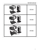
Page 23: ...23 Optional accessory Z5131X5 Z5132X5 Z5133X5 669419 236 669659 321 669648 281...

Page 24: ...9000 355385 Printed in Germany 1108 Es NEFF UK Ltd Grand Union House Old Wolverton Road Old Wolverton Milton Keynes MK12 5PT Tel 01908 328300 Fax 01908 328399...

Reviews: