25
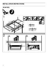
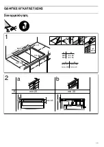
Assembly over oven, figure 2b
Hob: must have a minimum thickness of 30 mm.
Note:
If the distance between the hob and oven must be
increased, refer to the installation instructions for the oven.
Ventilation: The distance between the oven and the hob must
be at least 5 mm.
Installation above the dishwasher
An intermediate accessory must be installed. The accessory
may be ordered from our Technical Assistance Service. The
reference code for this accessory is 686002.
Worktop: Must have a minimum thickness of 20 mm and
maximum thickness of 40 mm.
The space between the top of the working surface and the top
of the dishwasher must be:
■
60 mm if installed over a compact dishwasher.
■
65 mm if installed over a full-size dishwasher.
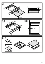
Ventilation, figure 4
Ventilating the hob requires:
■
An opening on the upper part of the kitchen unit's rear wall
(figure 4a)
.
■
A separation between the rear part of the kitchen unit and
kitchen wall
(figure 4b)
.
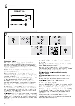
Installing the appliance, figures 5/6
Note:
Wear protective gloves to fit the hob. The non-visible
surfaces may have sharp edges.
Connect the appliance to the mains to check its working.
■
Voltage, see specifications plate.
■
Connect only according to the connection drawing
(figure 6)
.
1. Brown
2. Blue
3. Yellow and green
Changing the intensity of the 13 / 16 / 20 Amp
connection current, figure 7
Before using the hob for the first time, the intensity of the hob
connection must be tested.
Follow the steps below to change the current of the hob:
1.
Turn on the hob with the main switch. Do not place any pans
on the hotplates
2.
Within the following 60 seconds, adjust all hotplates to the
desired power level according to the required connection
current (see table).
3.
Turn off all the hotplates in sequence, starting from the lower
right and continuing counter-clockwise.
4.
The selected connection current is indicated in the display of
the right-hand lateral hotplates.
5.
Turn off the hob with the main switch.
The selected connection current will have been properly saved.
Uninstalling the appliance
Disconnect the appliance from the mains.
Push the hob upwards from below to remove it.
Caution!
Damage to the appliance! Do not try to remove the appliance
by prying it out from above.
Power level
Connection current in amperes
‚
20 A
ƒ
16 A
„
13 A
Summary of Contents for T B10 Series
Page 2: ...2 cm T B10...
Page 4: ...4 INSTRUCCIONES DE MONTAJE Montaje PLQ PLQ 5 PLQ PLQ PLQ PLQ PLQ PLQ PLQ PLQ PLQ PLQ D E...
Page 5: ...5 PLQ PLQ PLQ PLQ D E PLQ PLQ PLQ...
Page 22: ...22 INSTALLATION INSTRUCTIONS Assembly PLQ PLQ 5 PLQ PLQ PLQ PLQ PLQ PLQ PLQ PLQ PLQ PLQ D E...
Page 23: ...23 PLQ PLQ PLQ PLQ D E PLQ PLQ PLQ...
Page 39: ...39 PLQ PLQ 5 PLQ PLQ PLQ PLQ PLQ PLQ PLQ PLQ PLQ PLQ D E...
Page 40: ...40 PLQ PLQ PLQ PLQ D E PLQ PLQ PLQ...
Page 41: ...41 I 1 2 3 4 90 C 2a 9 9 9 1a 1 D E F...
Page 43: ...43 Produktinfo Internet www neff international com online shop www neff eshop com 8 8 8...
Page 44: ...44 2 cm...
Page 45: ...45 sandwich 90 2012 19 E waste electrical and electronic equipment WEEE...
Page 46: ...46 2 A Powerboost 3 Powerboost...
Page 47: ...47 20 4 1 9 1 2 10 9 4 20 20 9 1 1 1 2 1 2 1 2 3 4 3 4 3 4...
Page 50: ...50 1 10 10 30 1 Power Management 1000 W 1500 W 2000 W 10...
Page 51: ...51 1 2 10 4 3 4 5 4...
Page 52: ...52 3 E FD E FD 30 30 GR 18 182...
Page 55: ......

