background image

9

ELECTRICAL CONNECTIONS 


LOCAL AUTHORITY REQUIREMENTS 

Installation is only permitted by an authorised person, and carried out according to instructions provided by the 

manufacturer.  Incorrect  installation  might  cause  harm  and  damage  which  the  manufacturer  accepts  no 

responsibility. The electrical connection can be found at the bottom of the appliance, rear left hand side (looking 
from the front). 
 

INSTALLATION 

This cooktop must be connected to a 220-240V 50Hz power supply. It is earthed via the cord. 
Before  carrying  out  the  connection  to  the  power  supply,  the  voltage  rating  of  the  appliance  (stamped  on  the 

appliance identification plate) must be checked for correspondence to the available mains supply voltage, and the 

mains electric wiring should be capable of handling the hob’s power rating (also indicated on the identification 
plate); 
The power point must be connected to a suitable earth wiring, in conformity to current safety regulations. 
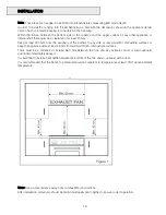
Ensure that the power supply is within 900 mm of the cooktop. The power supply cord must not touch against 

any hot surfaces and must be placed so that its temperature does not exceed 75ºC at any point along its length. 
The colours of the wires in the hob power cable may not correspond with the colours marked on the terminals of 

your electrical plug .The plug should in any case be wired as follows:   
-  Connect  the  green/yellow  wire  to  the  terminal  marked  with  the  letter  E  or  the  earth  symbol  or  coloured 

green/yellow; 
- Connect the blue wire to the terminal marked with the letter N or coloured black; 
- Connect the brown wire to the terminal marked with the letter L or coloured red. 
After having installed the appliance, the power switch or power plug must always be in an accessible position. 


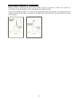
Electrical connection diagrams 
 
N.B  For  connections  to  the  mains  power  supply,  never  use  adapters,  reductions  or  multiple  power  points  as 

these may overheat and catch fire. 
In the event that installation should require modifications to the mains supply wiring system or if the power plug is 

not suitable for the type of power point available, it is required that a qualified technician be called to carry out 
substitution. 
The technician will also have to verify that the cross-section of the electric cables on the power point match the 
appliance’s power rating.   


Summary of Contents for NPC60G

Page 1: ...INSTALLATION OPERATION AND MAINTENANCE INSTRUCTIONS GAS COOKTOPS NPC60G AND NPC90G...

Page 2: ...ng and Maintenance 14 It is important that you retain these instructions proof of purchase as well as other important documents about this product for future reference Due to continual product develop...

Page 3: ...and cover the pan with a lid or fire blanket in order to smother the flame 9 If the electrical supply cord is damaged either when being installed or after installation it must be replaced by the manu...

Page 4: ...0 85 mm 10 0 MJ hr 1 55 mm 10 8 MJ hr Injector Diameter Wok Burner 1 10 mm 17 0 MJ hr 2 10mm 17 0 MJ hr NOTE The size of the injector diameter is stamped on the front face e g 1 8 for 1 80mm injector...

Page 5: ...ything e g flame tamer asbestos mat between pan and pan support as serious damage to the appliance may result Do not remove the pan support and enclose the burner with a wok stand as this will concent...

Page 6: ...all the appliance near flammable materials eg curtains The final act of any installation or gas type conversion must be the full testing of this appliance which includes leak testing ignition and func...

Page 7: ...the inlet adaptor at the end of the inlet manifold using two spanners note orientation of the NG regulator gas flow Connect the other side of the NG regulator to the gas inlet pipe with the correct B...

Page 8: ...gas to flow through the valve at the minimum control knob setting This can be checked after the gas has been connected by running the cooktop for a 10 seconds MAX and then quickly turning down to MIN...

Page 9: ...inst any hot surfaces and must be placed so that its temperature does not exceed 75 C at any point along its length The colours of the wires in the hob power cable may not correspond with the colours...

Page 10: ...periphery of the burners to any side or rear wall with combustible surfaces or keep the appliance sides at least 45 mm from walls with non combustible surfaces There must be a distance of at least 65...

Page 11: ...this is not required Installation of an oven without a cooking fan underneath the hob is forbidden A distance of at least 150 mm is required between the sides of the cooktop and any internal wall of...

Page 12: ...w the products of combustion of the gas appliance to be discharged see diagrams below If this is not possible an electric fan may be used attached to the external wall or the ceiling above the cooktop...

Page 13: ...ed to electricity If connected ensure that the gas is turned on and that the electrodes are sparking Also ensure that all parts of the burner are correctly positioned USING THE BURNERS For greater eff...

Page 14: ...skirt For wok burners the first operation is similar to that for semi rapid and rapid burners Once positioned there are two steel burner covers to be placed on top of the brass burner skirt The outer...

Page 15: ...15...

Page 16: ...itchen By Omega Products are distributed in Australia by Shriro Australia Pty Ltd Locked Bag 5002 Kingsgrove NSW 2208 Phone 131 NPK Fax 02 9415 5525 Email service shriro com au Website www neilperryki...

Reviews: