background image


11 


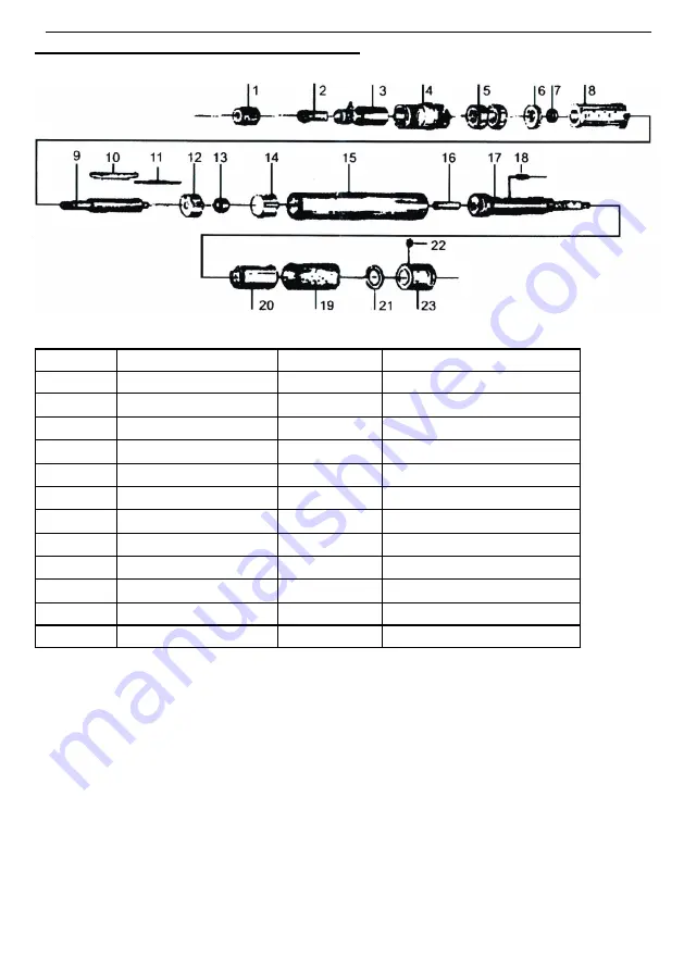
ASSEMBLY DIAGRAM AND PARTS LIST 


INDEX NO.  DESCRIPTION 

INDEX NO. 

DESCRIRTION 

CLAMPING NUT 

13 

BALL BEARING 

COLLET 

14 

INTAKE PLATE 

FRONTCOVER 

15 

SLEEVE 

COLLET FONDATION 

16 

INTAKE STEELTUBE 

BALLBEARING 

17 

HOSE PLUG 

SPACER 

18 

PIN 

LATERAL DISC 

19 

SLIDING KNOB 

CYLINDER 

20 

0 RING 

ROTOR 

21 

0 RING 

10 

FIBRE VANES 

22 

SCREW 

11 

PIN 

23 

REAR END HOLDER 

12 

BEARING PLATE 


Summary of Contents for CT3073

Page 1: ...RINDER KIT CT3073 ORIGINAL INSTRUCTIONS Cannon Tools Limited Address 20 Station Road Rowley Regis West Midlands B65 0JU U K SAVE THESE INSTRUCTIONS AND PRECAUTIONS READ ALL PRECAUTONS AND INSTRUCTIONS...

Page 2: ...Directive based on its design and type as brought into circulation by us In case of alteration of the machine not agreed upon by us this declaration will lose its validity Product description AIR MIC...

Page 3: ...lting in the ignition of the dust or fumes 3 Keep bystanders children and visitors away while operating the tool Distractions are able to result in the loss of control of the tool Personal Safety 1 St...

Page 4: ...orrect tool for the application The correct tool will do the job better and safer at the rate for which the tool is designed 3 Do not use the tool if the switch does not turn the tool on or off Any to...

Page 5: ...h or break during operation 4 Obey the manual for the air compressor used to power this tool 5 Install an in line shutoff valve to allow immediate control over the air supply in an emergency even if a...

Page 6: ...nts and Controls INITIAL SETUP ASSEMBLY Air Supply WARNING To prevent serious injury from explosion use only clean dry regulated compressed air to power this tool Do not use oxygen carbon dioxide comb...

Page 7: ...Operation section for description of controls 4 Close the in line shut off valve between the compressor and the tool 5 Turn on the air compressor according to the manufacturer s directions and allow...

Page 8: ...and injury 2 Route the air hose along a safe route to reach the work area without creating a tripping hazard or exposing the air hose to possible damage The air hose must be long enough to reach the...

Page 9: ...ts off position before performing any inspection maintenance or cleaning procedures TO PREVENT SERIOUS INJURY FROM TOOL FAILURE Do not use damaged equipment If abnormal noise vibration or leaking air...

Page 10: ...5 Have qualified technician clean and lubricate mechanism Install in line filter in air supply as stated in Setup Air Supply 6 Replace all vanes Severe air leakage Slight air leakage is normal especi...

Page 11: ...NUT 13 BALL BEARING 2 COLLET 14 INTAKE PLATE 3 FRONTCOVER 15 SLEEVE 4 COLLET FONDATION 16 INTAKE STEELTUBE 5 BALLBEARING 17 HOSE PLUG 6 SPACER 18 PIN 7 LATERAL DISC 19 SLIDING KNOB 8 CYLINDER 20 0 RI...

Page 12: ...12 CANNON TOOLS LTD Add 20 station road Rowley Regis west midlands B65 0JU U K Made in China...

Reviews: