background image

5. Technical data 

Model 

KIMO 24V


Force exerted by thrust (F

N

100N 

Force exerted by traction (F

N

200N 

Strokes (S

V

70, 125, 170, 210 mm 

Power supply voltage (U

N

24 V

  SELV 

Rated absorbed current (I

N

0,36A 

Power absorbed at nominal load (P

N

8,6W 

Electrical insulation 

Class III 

No load speed 

5,5 mm/s 

Duration of no load stroke 

(210 mm) 

38 s 

Type of service (D

R

5 cycles 

Operating temperature 

- 5  + 65 ºC 

Protection index for electrical devices 

IP32 

Adjustment of connection to window frame  

Automatic definition of position 

Parallel powering of two or more motors 

YES 

(max 20 actuators)


Operation with BK-LOCK electromechanical 
lock  

Yes 

Synchronised function 

Not foreseen 

Holding nominal force 

(it can vary according to 

the chosen brackets)


1.700N 

Stroke-end at opening 

Electronic by dip-switch 

Stroke-end at closing 

At absorption of power 

Chain exit 

Central 

Length of power cable 

2 m 

Dimensions 

29x29x310 mm 

Weight 

0,720 Kg 

The data indicated in these figures is not binding and is subject to variation without notification. 

6. Id plate and marking data 

The KIMO actuators have CE marking and comply  with the Standards listed  in the 
Declaration of Conformity. They also come with a Declaration of Incorporation, due 
to  their  classification  by  the  Machinery  Directive  as  “partly  completed  machines”. 
Both declarations are included in the final pages of this manual. 
The plate data is displayed on an adhesive label placed on the outside of the casing, 
which must remain intact and visible.  
The main  information  it displays  includes: manufacturer's  address,  product  name - 
model number, technical characteristics, production date and serial number. 
In the event of a complaint, please indicate the serial number (SN) displayed on the 
label.  
An  explanation  of  the  symbols  used  on  the  label  to  abbreviate  the  technical 
characteristics is given in the table in the chapter on “TECHNICAL DATA”. 

7. Electric power supply 

The  KIMO  actuator  is  powered  with  a  voltage  of  24V

  SELV.  The  power  supply 

cable has three conductors: the first conductor 

R

ED 

“1”

 that should be connected to 

the + (positive) C

LOSES

 the window; the second conductor 

B

LACK 

“2”

 that should be 

connected  to  the  + (positive)  O

PENS

  the  window;  the  third  conductor 

G

REEN

  “3”

  is 

the conductor used for the BK-LOCK control communication signal

.  

The  24V

  low-voltage  actuators  can  be  powered  using  a  station  with  emergency 

batteries or a security power supply unit with an output voltage of 24V


(min. 20.4V, 

max. 28,8V

), that is to say, sized based on the number of actuators connected.  

7.1. 

Selecting the cross-section of the power supply cables 

It  is  necessary  to  check  the  cross-section  of  the  cable,  which  should  be  calculated 
based on the length of the cable itself. The table below specifies the maximum length 
of the cables for connection of a motor. 

CABLE SECTION 

Actuator fed at 

24V 


0.50 mmq 

~40 m 

0.75 mmq 

~60 m 

1.00 mmq 

~80 m 

1.50 mmq 

~120 m 

2.50 mmq 

~200 m 

4.00 mmq 

~320 m 

6.00 mmq 

~480m 

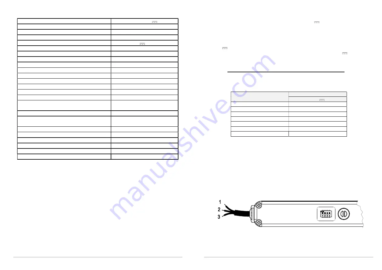
8. Electrical connection 

The  machines  are  equipped  with  a  power  supply  cable  constructed  in  compliance 
with safety standards and restrictions on radio-frequency interference.  
The power supply cable - with conductors having a cross-section of 0.5 mm²  - is 2 
meters long with different colored conductors, as follows 

  1


R

ED

-coloured conductor; 

  2


B

LACK

-coloured conductor; 

  3


G

REEN

-coloured conductor: 


For harness, please follow this diagram:


Summary of Contents for KIMO 24V

Page 1: ...stment is required CAUTION if the power cable is damaged it must be replaced by qualified personnel from a service centre authorised by the manufacturer CAUTION Disconnect the power supply during cleaning or maintenance operations Do not use solvents or jets of water to wash the appliance the appliance should not be submerged in water In the event of fault or malfunction switch off the device at t...

Page 2: ...ced physical sensory or mental capabilities or lacking experience and knowledge Do not allow children to play out of their reach The actuator is destined exclusively for installation indoors For any special application we recommend you consult the manufacturer beforehand After removing packaging check f 4 AREFULLY OBSERVE ALL THE FOLLOWING INSTALLATION INSTRUCTIONS ENSURE PERSONAL SAFETY IMPROPER ...

Page 3: ...BK lock also as a building security system it is actuator not be used for any other purpose unless approved manufacturer beforehand with the supplier of the entire system in any case retaining sole liability The actuator is manufactured in accordance with the EC Directives and Regulations listed in the attached Declaration of Incorporation and Conformity Electrical connections must conform to regu...

Page 4: ...r technical characteristics production date and serial number In the event of a complaint please indicate the serial number SN displayed on the label An explanation of the symbols used on the label to abbreviate the technical characteristics is given in the table in the chapter on TECHNICAL DATA 8 7 Electric power supply The KIMO actuator is powered with a voltage of 24V SELV The power supply cabl...

Page 5: ...lled Check that once the actuator has been installed chain completely in the window is perfectly closed If this is not the case the actuator will not function correctly as the window will not close correctly 10 9 1 Preparation for mounting the actuator Before beginning to mount the actuator depending on the type of application the window frame must be prepared by carrying out the following operati...

Page 6: ...h No 2 the instructions in the BK LOCK Power the two machines with a voltage of 24V inverting the polarity to open and close the system Powering Black wire with 24V effects the lock moves in the opening direction the lock arrives at stroke the chain actuator begins opening opening the movable sash the KIMO chain actuator reaches stroke Powering Red wire with 24V effects the chain actuator moves in...

Page 7: ...osition by the chain 4 After maintenance and or cleaning repeat points 1 and 2 in reverse order 14 Troubleshooting Possible causes of malfunction during installation or use Problem Actuator does not work 15 ENVIRONMENTAL PROTECTION All materials used in the manufacture of this appliance are recyclable We recommend that the device itself and any accessories packaging etc be sent to a centre for eco...

Page 8: ...2014 30 EU Direttiva Compatibilità Elettromagnetica ElectroMagnetic Compatibility Directive EMCD 2014 35 EU Direttiva Bassa Tensione Low Voltage Directive LVD 2011 65 EU Direttiva sulla restrizione dell uso di determinate sostanze pericolose nelle apparecchiature elettriche ed elettroniche Direttiva RoHS Restriction of the use of certain hazardous substances Directive RoHS Directive 2015 863 EU Di...

Reviews: