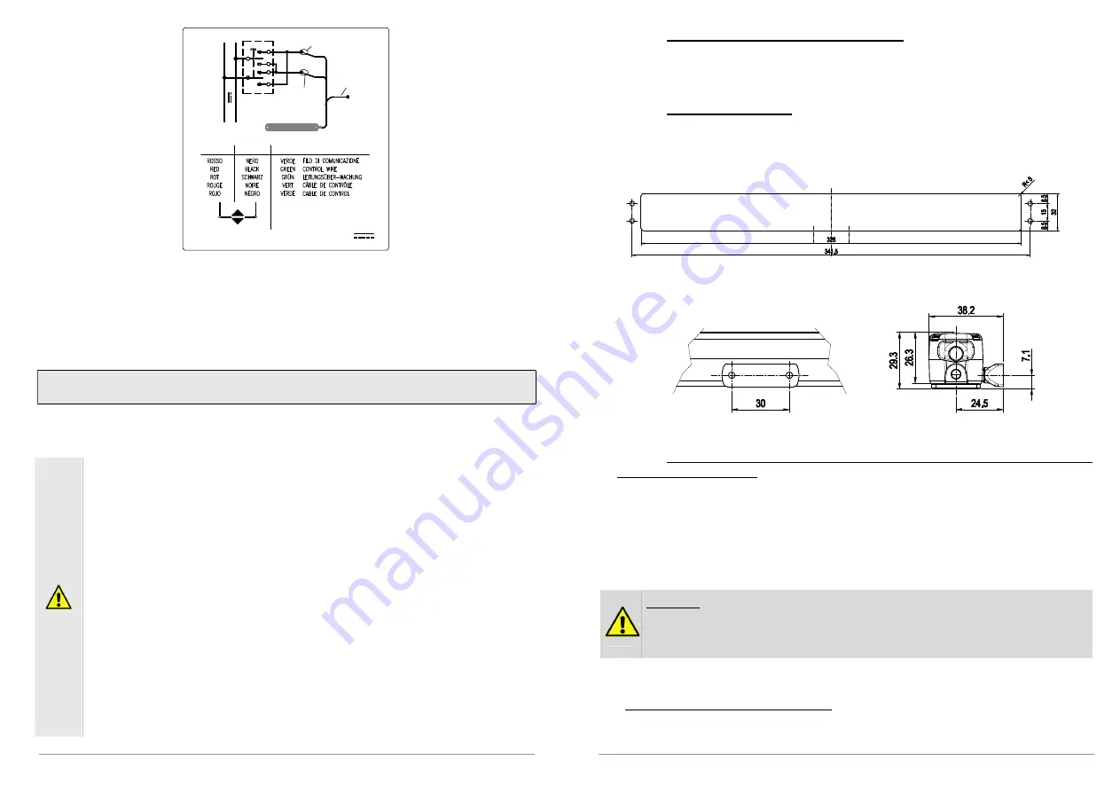
background image

- +

24

V

3

1

2

1

2

3

24V


Note:

 the first conductor 

R

ED 

“1”

 that should be connected to the + (positive) C

LOSES


the  window;  the  second  conductor 

B

LACK

  “2”

  that  should  be  connected  to  the  + 

(positive) O

PENS

 the window; the third conductor 

 G

REEN

 “3”

 is the conductor used for 

the BK-LOCK control communication signal. 

9. Instructions for assembly 

These indications are for specialised technical personnel and basic work and 

safety techniques are not indicated. 

All  preparatory,  assembly  and  electrical  connection  operations  must  be  performed 
by specialised technical personnel to guarantee optimal function and service of the 
actuator. Check that the following fundamental conditions have been met: 


Before installing the actuator, check that the moving parts of the window on 
which  it  is  to  be  installed  are  in  perfect  working  condition  and  that  they 
open and close properly and are well balanced (where applicable).  
Actuator  specifications  must  be  sufficient  for  movement  of  the  window 
without encountering any obstacle. The limits indicated in the technical data 
table  must  not  be  superseded 

(page  7)

  and  the  most  appropriate  stroke 

should  be  selected.  Calculations  should  be  checked  using  the  formula 
indicated on page 5. 

Attention.

  Check  that  the  electrical  power  supply  corresponds  to  that 

indicated on the 

TECHNICAL DATA

 label on the machine. 

Ensure  that  the  actuator  has  not  been  damaged  during  transport,  first 
visually and then by powering in both directions. 
Check that the width of the inside of the window (where the actuator is to 
be  assembled)  is  over  360  mm,  otherwise  the  actuator  should  not  be 
installed. 
Check that  once  the  actuator  has  been  installed,  chain  completely  in,  the 
window  is  perfectly  closed.  If  this  is  not  the  case  the  actuator  will  not 
function correctly as the window will not close correctly. 

10 

9.1. 

Preparation for mounting the actuator 

Before  beginning  to  mount  the  actuator,  depending  on  the  type  of  application,  the 
window frame must be prepared by carrying out the following operations. 

9.2. 

Recessed mounting 

For recessed mounting, the window frame must be prepared by milling and making 
two  holes  as  indicated  in  the  diagram  below.  The  depth  of  the  milling  must  be  at 
least 30 mm. 


Then  make  two  Ø4.5  holes  on  the  sash  for  the  attachment  bracket.  The 
measurements are specified in the diagram below. 


9.3. 

Surface  mounting  on  top-hung  windows  opening  outwards  or 

bottom-hung windows 

The actuator can also be surface mounted on top-hung windows opening outwards or 
dormer windows and on bottom-hung windows, however for these specific applications 
special  support  brackets  are  required  for  the  actuator  which  must  be  supplied 
separately.  
The  two  half-brackets  attaching  the  actuator  to  the  sash,  however,  are  the  same 
standard brackets supplied with the actuator and included in the package.  


Warning

.  In  order  to  prevent  unpleasant  mishaps  with  the  machine  and 

possible safety hazards, carefully choose the length of the clamping screws 
in  order  to  avoid  damaging  the  power  supply  cables  during  the  mounting 
procedure. 

In order to carry out a cost-effective and precise up-to-standard work, it is best if you 
prepare the following complementary material: small parts, equipment and tools. 


Fastening on metal window frames: M4 threaded inserts 

(2 pieces for recessed 

mounting and 4 pieces for surface mounting)

, M4x12 flat head metric screws 

(2 

pieces (4 pieces for surface mounting))

Summary of Contents for KIMO 24V

Page 1: ...stment is required CAUTION if the power cable is damaged it must be replaced by qualified personnel from a service centre authorised by the manufacturer CAUTION Disconnect the power supply during cleaning or maintenance operations Do not use solvents or jets of water to wash the appliance the appliance should not be submerged in water In the event of fault or malfunction switch off the device at t...

Page 2: ...ced physical sensory or mental capabilities or lacking experience and knowledge Do not allow children to play out of their reach The actuator is destined exclusively for installation indoors For any special application we recommend you consult the manufacturer beforehand After removing packaging check f 4 AREFULLY OBSERVE ALL THE FOLLOWING INSTALLATION INSTRUCTIONS ENSURE PERSONAL SAFETY IMPROPER ...

Page 3: ...BK lock also as a building security system it is actuator not be used for any other purpose unless approved manufacturer beforehand with the supplier of the entire system in any case retaining sole liability The actuator is manufactured in accordance with the EC Directives and Regulations listed in the attached Declaration of Incorporation and Conformity Electrical connections must conform to regu...

Page 4: ...r technical characteristics production date and serial number In the event of a complaint please indicate the serial number SN displayed on the label An explanation of the symbols used on the label to abbreviate the technical characteristics is given in the table in the chapter on TECHNICAL DATA 8 7 Electric power supply The KIMO actuator is powered with a voltage of 24V SELV The power supply cabl...

Page 5: ...lled Check that once the actuator has been installed chain completely in the window is perfectly closed If this is not the case the actuator will not function correctly as the window will not close correctly 10 9 1 Preparation for mounting the actuator Before beginning to mount the actuator depending on the type of application the window frame must be prepared by carrying out the following operati...

Page 6: ...h No 2 the instructions in the BK LOCK Power the two machines with a voltage of 24V inverting the polarity to open and close the system Powering Black wire with 24V effects the lock moves in the opening direction the lock arrives at stroke the chain actuator begins opening opening the movable sash the KIMO chain actuator reaches stroke Powering Red wire with 24V effects the chain actuator moves in...

Page 7: ...osition by the chain 4 After maintenance and or cleaning repeat points 1 and 2 in reverse order 14 Troubleshooting Possible causes of malfunction during installation or use Problem Actuator does not work 15 ENVIRONMENTAL PROTECTION All materials used in the manufacture of this appliance are recyclable We recommend that the device itself and any accessories packaging etc be sent to a centre for eco...

Page 8: ...2014 30 EU Direttiva Compatibilità Elettromagnetica ElectroMagnetic Compatibility Directive EMCD 2014 35 EU Direttiva Bassa Tensione Low Voltage Directive LVD 2011 65 EU Direttiva sulla restrizione dell uso di determinate sostanze pericolose nelle apparecchiature elettriche ed elettroniche Direttiva RoHS Restriction of the use of certain hazardous substances Directive RoHS Directive 2015 863 EU Di...

Reviews: