background image

Tel-A-Greeter 204


10 

Rev. 04/19/2000 

Installation 

 
Physical installation 

 
Locate the Tel-A-Greeter near the phone company boxes of the telephone lines the 
unit is to answer. The Tel-A-Greeter must be installed directly to the CO lines, before 
any  KSU,  PBX,  or  other  equipment.    If  you  are  not  familiar  with  how  your  phone 
system  is  installed,  or  do  not  know  which  lines  go  directly  to  your  phone  company 
please find a qualified person to perform the installation. 
 
The following instructions describe a typical installation utilizing lines 2, 3, and 4 for 
call  answering  and  line  1  for  MOH.    However,  if  desired,  you  can  configure  all  four 
channels  for  call  answering,  leave  one  or  more  lines  unused,  or  any  other 
configuration that suits your requirements.  

The ProAmp is an optional accessory 

and may not be included with your system.  


– Connecting the phone lines 

For  standard  phone  lines  not  connected  to  a  KSU/PBX:    Connect  the 
selected  CO  lines  to  the  TAG’s  telco  line  inputs  using  RJ-11  to  RJ-11 
cables (included).   
 
For a phone line connected to a KSU/PBX:  Disconnect the selected CO 
lines from the KSU/PBX and connect to the TAG’s telco line inputs using 
th

e lines’ existing RJ-11 cables. 


– Connecting the local program telephone (optional) 

Connect a standard analog phone (home phone) to the program jack on 
the  Tel-A-

Greeter’s  rear  panel  using  an  RJ-11  to  RJ-11  cable  (not 

included).   


– Connecting the MOH output channel 

Select the line to be used for MOH audio and connect its telco input jack 
on the TAG’s rear panel to the ProAmp’s AUDIO IN jack using an RJ-11 
to RCA cable (included). 


– Connecting the power supplies 

Plug  the  Tel-A-

Greeter’s  power  supply  (12V  DC,  500mA,  center-pin-

positive)  into  a  110V  AC  outlet  (not  controlled  by  a  wall  switch)  and  the 
12VDC  jack  on  the  TAG.    Plug  the  ProAmp’s  power  supply  (12V  DC, 
500mA,  center  pin  positive)  into  a  110V  AC  outlet  (not  controlled  by  a 
wall switch) and t

he 12VDC jack on the ProAmp’s front panel. 


– Connecting the phone system MOH port 

Connect  the  phone system’s MOH port to the 600Ω or 8Ω AUDIO OUT 
jack on the ProAmp using an RCA to RCA cable (included).  Consult the 

Summary of Contents for Tel-A-Greeter 204

Page 1: ...Tel A Greeter 204 Rev 04 19 2000 Tel A Greeter 204 Installation Operation Instructions Please leave these instructions with the unit at all times Comment EC1...

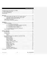
Page 2: ...one lines 10 2 Connecting the local program telephone optional 10 3 Connecting the MOH output channel 10 4 Connecting the power supplies 10 5 Connecting the phone system MOH port 10 Final installation...

Page 3: ...Tel A Greeter 204 3 Rev 04 19 2000 Reference Information 19 Frequently asked questions 19 Command summary 20 Default settings 20...

Page 4: ...Failure to follow Nel Tech Labs Inc installation operation or maintenance instructions Unauthorized modification or alteration of the product or its components Product abuse misuse or the negligent a...

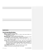
Page 5: ...ecifications Tel A Greeter Specifications Media Internal flash memory storage Sampling Method Storage Audio is stored in 8 bit law format at a sampling rate of 8 kHz Message Length 8 minutes 4MB total...

Page 6: ...ProAmp together ProAmp Specifications Power Required 12VDC power supply included with the unit provides 12VDC 500mA center pin positive from a nominal 110 VAC source Input RCA jack for line level audi...

Page 7: ...s long This provides the capability to play a different message for each of the four lines Initially message 1 is assigned to line 1 message 2 to line 2 message 3 to line 3 and message 4 to line 4 How...

Page 8: ...e to the MOH line Line s to be Answered The TAG normally answers three phone lines with line 4 reserved for MOH However if desired all four channels can be used for call answering Note the TAG can onl...

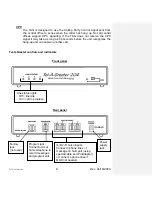
Page 9: ...as long as 90 seconds before the unit recognizes the hang up and can answer another call Tel A Greeter controls and indicators Front panel Rear panel Factory jack not used Program jack Connect normal...

Page 10: ...telco line inputs using RJ 11 to RJ 11 cables included For a phone line connected to a KSU PBX Disconnect the selected CO lines from the KSU PBX and connect to the TAG s telco line inputs using the l...

Page 11: ...phone system end of this connection not included Installation Diagram Note Each line used as a continuous play audio source MOH mode requires a separate ProAmp and special RJ 11 to RCA connector cabl...

Page 12: ...ny messages you will use Set the mode for each line using the set line to day mode and or set line to MOH mode commands as needed The default configuration sets lines 1 through 4 to day mode Assign a...

Page 13: ...e line and plays a triple beep indicating it is in command mode Remote Through the use of a phone installed on a different line Control is seized by calling the phone number of a line connected to one...

Page 14: ...0 3 Delete message number 3 7 0 0 4 Delete message number 4 Record message Allows the user to record messages If the message already exists you must first delete it before recording see delete messag...

Page 15: ...0 4 Review message number 4 Set line message number Sets which message number will play on which line number Valid message number range is 01 04 Syntax 4 1 X X Set line 1 to play message number XX 4 2...

Page 16: ...o day mode Syntax 0 1 0 1 Set line 1 to day mode 0 1 0 2 Set line 2 to day mode 0 1 0 3 Set line 3 to day mode 0 1 0 4 Set line 4 to day mode Set line to MOH mode Sets a line to MOH mode Syntax 0 3 0...

Page 17: ...X any value 0000 9999 9 2 X X X X Set master password to XXXX IMPORTANT NOTE If you forget or lose your master password you will be unable to seize control of the unit unless you use the restore defa...

Page 18: ...This booklet is available from the U S Government Printing Office Washington D C 20402 Changes and Modifications not expressly approved by the manufacturer or registrant of this equipment can void yo...

Page 19: ...umber of terminals allowed to be connected to a telephone interface The termination on an interface may consist of any combination of devices subject only to the requirement that the sum of the Ringer...

Page 20: ...of beeps 1 4 beeps indicates message number assigned to line X Set line message number 4X YY X 1 4 YY 01 04 Sets line X to play message number YY Master password 92 XXXX 0000 9999 Sets the master pas...

Page 21: ...Tel A Greeter 204 21 Rev 04 19 2000...

Reviews: