Technical Discussion
104
Circuit Analysis
The following paragraphs discuss the operation of each of the printed circuit
boards within the N-550 pulse oximeter. (Refer to the appropriate schematic
diagram at the end of this section, as necessary).
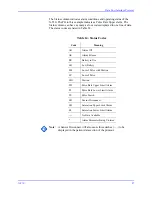
Table 16: MP-506 J2 Pinouts
Pin
Signal
1
C
-
LOCK Input
2
Ground
3
Ground
4
Reset Input
5
Ground
6
+12 V Power Input
7
Analog Output
8
TX Transmit data output from MP
-
506
9
RX Receive data input to MP
-
506
10
+5 V Analog Power Input
11
CTS (Clear to Send) input to MP
-
506
12
Ground
13
+5 V Digital Power input
14
Ground
Summary of Contents for OxiMax N-550
Page 1: ...N 550 Pulse Oximeter Service Manual min min SpO2 N 550 SatSeconds SpO2 ...
Page 10: ...Blank Page ...
Page 38: ...Blank Page ...
Page 64: ...Blank Page ...
Page 81: ...Disassembly Guide N 550 71 Figure 39 Equipotential Ground Terminal Removed ...
Page 82: ...Blank Page ...
Page 86: ...Spare Parts 76 Figure 40 Exploded View ...
Page 90: ...Blank Page ...
Page 108: ...Blank Page ...
Page 120: ...Blank Page ...
Page 130: ...Figure 56 Main PCB Parts Locator Diagram 129 Technical Description N 550 ...
Page 131: ...Figure 57 Front Panel Parts Locator Diagram 131 N 550 Technical Description ...
Page 136: ...Blank Page ...
Page 137: ... ...


