Disassembly Guide
N-550
63
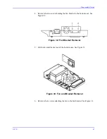
5. Disconnect the ribbon cable connector, item 3, from the front case PCB.
6. Remove the bracket screw connected to the main PCB. See Figure 18
item 1.
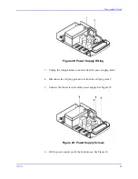
Figure 25: Front Case Mounting Screws
7. Remove the bracket screw, item 2, connected to the front PCB.
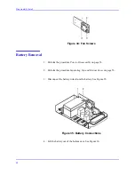
8. Remove the front panel assembly from the top case assembly.
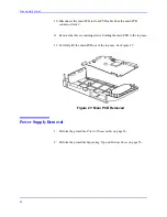
9. Disconnect the MP-506 to main PCB cable from the main PCB connector.
Figure 26: Main PCB Removal
Summary of Contents for OxiMax N-550
Page 1: ...N 550 Pulse Oximeter Service Manual min min SpO2 N 550 SatSeconds SpO2 ...
Page 10: ...Blank Page ...
Page 38: ...Blank Page ...
Page 64: ...Blank Page ...
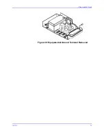
Page 81: ...Disassembly Guide N 550 71 Figure 39 Equipotential Ground Terminal Removed ...
Page 82: ...Blank Page ...
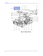
Page 86: ...Spare Parts 76 Figure 40 Exploded View ...
Page 90: ...Blank Page ...
Page 108: ...Blank Page ...
Page 120: ...Blank Page ...
Page 130: ...Figure 56 Main PCB Parts Locator Diagram 129 Technical Description N 550 ...
Page 131: ...Figure 57 Front Panel Parts Locator Diagram 131 N 550 Technical Description ...
Page 136: ...Blank Page ...
Page 137: ... ...


