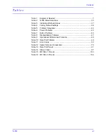
Contents
vi
Figure 49: Main PCB Isolation for Interface Schematic Diagram .................... 115
Figure 50: Main PCB DC/Battery Input and DC/DC Schematic Diagram ....... 117
Figure 51: Main PCB Interface and Speaker Control Schematic Diagram ..... 119
Figure 52: Main PCB MCU and Storage Control Schematic Diagram ............ 121
Figure 53: Front Panel 7-Segment Display Schematic Diagram .....................123
Figure 54: Front Panel LED Display and Buttons Schematic Diagram ........... 125
Figure 55: Front Panel Interface and Drivers Schematic Diagram .................. 127
Figure 56: Main PCB Parts Locator Diagram ..................................................129
Figure 57: Front Panel Parts Locator Diagram ............................................... 131
Figure 58: Power Supply Parts Locator Diagram ............................................ 133
Summary of Contents for OxiMax N-550
Page 1: ...N 550 Pulse Oximeter Service Manual min min SpO2 N 550 SatSeconds SpO2 ...
Page 10: ...Blank Page ...
Page 38: ...Blank Page ...
Page 64: ...Blank Page ...
Page 81: ...Disassembly Guide N 550 71 Figure 39 Equipotential Ground Terminal Removed ...
Page 82: ...Blank Page ...
Page 86: ...Spare Parts 76 Figure 40 Exploded View ...
Page 90: ...Blank Page ...
Page 108: ...Blank Page ...
Page 120: ...Blank Page ...
Page 130: ...Figure 56 Main PCB Parts Locator Diagram 129 Technical Description N 550 ...
Page 131: ...Figure 57 Front Panel Parts Locator Diagram 131 N 550 Technical Description ...
Page 136: ...Blank Page ...
Page 137: ... ...


