Introduction
2
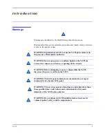
Cautions
Cautions are identified by the CAUTION symbol shown above.
Cautions alert the user to exercise care necessary for the safe and effective use
of the N-595 pulse oximeter.
Caution: Observe ESD (electrostatic discharge) precautions when
working within the unit.
Caution: Observe ESD (electrostatic discharge) precautions when
disassembling and reassembling the N-595 and when handling any of the
components of the N-595.
Caution: When reassembling the N-595, tighten the screws that hold the
cases together to a maximum of 10 inch-pounds. Over-tightening could
strip out the screw holes in the top case, rendering it unusable.
Caution: When installing the Power Supply or the User Interface PCB,
tighten the seven screws to a maximum of 4 inch-pounds. Over-tightening
could strip out the screw holes in the bottom case, rendering it unusable.
Manual
Overview
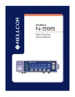
This manual contains information for servicing the Nellcor
®
model
N-595 pulse oximeter. Only qualified service personnel should service this
product. Before servicing the N-595, read the operator's manual carefully for
a thorough understanding of safe operation of the N-595.
WARNING: Explosion hazard. Do not use the N-595 pulse oximeter in
the presence of flammable anesthetics.
Description of
N-595 Monitor
The N-595 Monitor is intended for the continuous non-invasive monitoring of
functional oxygen saturation of arterial hemoglobin (SpO
2
) and pulse rate.
The N-595 is intended for use with neonatal, pediatric, and adult patients
during both no-motion and motion conditions and for patients who are well or
poorly perfused, in hospitals, hospital-type facilities, intra-hospital transport,
and home environments. For prescription use only.
Note:
Hospital use typically covers such areas as general care floors,
operating rooms, special procedure areas, intensive and critical care
areas, within the hospital plus hospital-type facilities. Hospital-type
facilities include physician office based facilities, sleep labs, skilled
nursing facilities, surgicenters, and sub-acute centers.
Summary of Contents for OXIMAX N-595
Page 1: ......
Page 8: ...This page intentionally left blank...
Page 13: ...Introduction N 595 5 Figure 4 Trend Softkey Map...
Page 50: ...This page intentionally left blank...
Page 76: ...This page intentionally left blank...
Page 82: ...This page intentionally left blank...
Page 96: ...This page intentionally left blank...
Page 98: ...Data Port Interface Protocol 90 Figure 19 Data Port Setup...
Page 116: ...This page intentionally left blank...
Page 125: ...Figure 27 Main PCB Schematic Diagram Sheet 1 of 13 117...
Page 126: ...Figure 28 Main PCB Schematic Diagram Sheet 2 of 13 119...
Page 127: ...Figure 29 Main PCB Schematic Diagram Sheet 3 of 13 121...
Page 128: ...Figure 30 Main PCB Schematic Diagram Sheet 4 of 13 123...
Page 129: ...Figure 31 Main PCB Schematic Diagram Sheet 5 of 13 125...
Page 130: ...Figure 32 Main PCB Schematic Diagram Sheet 6 of 13 127...
Page 131: ...Figure 33 Main PCB Schematic Diagram Sheet 7 of 13 129...
Page 132: ...Figure 34 Main PCB Schematic Diagram Sheet 8 of 13 131...
Page 133: ...Figure 35 Main PCB Schematic Diagram Sheet 9 of 13 133...
Page 134: ...Figure 36 Main PCB Schematic Diagram Sheet 10 of 13 135...
Page 135: ...Figure 37 Main PCB Schematic Diagram Sheet 11 of 13 137...
Page 136: ...Figure 38 Main PCB Schematic Diagram Sheet 12 of 13 139...
Page 137: ...Figure 39 Main PCB Schematic Diagram Sheet 13 of 13 141...
Page 138: ...Figure 40 Main PCB Assembly Drawing Front View 143...
Page 141: ...Figure 43 Linear Power Supply Assembly Drawing 149 AC FERRITE DC FERRITE...

