Data Port Interface Protocol
96
The SpaceLabs monitor provides both audible and visual alarm indications
for equipment interfaced through the Universal FlexPort
TM
interface module.
Silencing the N-595 alarms will also silence the SpaceLabs monitor alarms.
The monitors must be able to sound an audible alarm in order to maintain
patient safety.
Note:
The parameters setup for the SpaceLabs bedside monitor interface
may be saved as institutional default settings. See
Setting Industrial
Defaults (Sample)
page 40. Use care when performing this procedure
because all settings will be saved as institutional default settings.
Marquette
Communications
The N-595 sends SpO
2
, pulse rate, and alarm status data to the Marquette
monitor.
The Marquette monitor requires an Octanet
TM
interface module to interface
with the N-595 pulse oximeter. The interface module comes with an interface
cable, GE Marquette part number 417961-033, that connects to the Nellcor
interface cable.
The RS-232 hardwire interface cable has a DB-15 connector for the
N-595 and the applicable connector for the Marquette Octanet
TM
interface
module cable. Nellcor cable part number 902254 is recommended for this
interface.
Corrupt data will be indicated by a Communications Error displayed on the
Marquette monitor.
When the N-595 is in the Marquette mode of operation the interface baud rate
is automatically set to 9,600 bits per second.
The GE Marquette monitor only sounds audible alarms for equipment
interfaced through the Octanet
TM
interface module. Silencing the
N-595 audible alarm has no effect on the GE Marquette monitor sounding an
alarm.
Note:
The parameters setup for the Marquette bedside monitor interface
may be saved as institutional default settings. See
Setting Industrial
Defaults (Sample)
page 40. Use care when performing this procedure
because all settings will be saved as institutional default settings.
Datex-Ohmeda
Communications
The Datex-Ohmeda monitor AS/3 must be configured for communications
with the Nellcor N-200 monitor in order to communicate with the N-595
monitor. Refer to the AS/3 operator's manual for instructions on configuring
the AS/3 monitor.
The N-595 sends SpO
2
, pulse rate, and alarm status data to the Datex AS3
monitor.
Summary of Contents for OXIMAX N-595
Page 1: ......
Page 8: ...This page intentionally left blank...
Page 13: ...Introduction N 595 5 Figure 4 Trend Softkey Map...
Page 50: ...This page intentionally left blank...
Page 76: ...This page intentionally left blank...
Page 82: ...This page intentionally left blank...
Page 96: ...This page intentionally left blank...
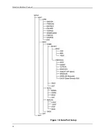
Page 98: ...Data Port Interface Protocol 90 Figure 19 Data Port Setup...
Page 116: ...This page intentionally left blank...
Page 125: ...Figure 27 Main PCB Schematic Diagram Sheet 1 of 13 117...
Page 126: ...Figure 28 Main PCB Schematic Diagram Sheet 2 of 13 119...
Page 127: ...Figure 29 Main PCB Schematic Diagram Sheet 3 of 13 121...
Page 128: ...Figure 30 Main PCB Schematic Diagram Sheet 4 of 13 123...
Page 129: ...Figure 31 Main PCB Schematic Diagram Sheet 5 of 13 125...
Page 130: ...Figure 32 Main PCB Schematic Diagram Sheet 6 of 13 127...
Page 131: ...Figure 33 Main PCB Schematic Diagram Sheet 7 of 13 129...
Page 132: ...Figure 34 Main PCB Schematic Diagram Sheet 8 of 13 131...
Page 133: ...Figure 35 Main PCB Schematic Diagram Sheet 9 of 13 133...
Page 134: ...Figure 36 Main PCB Schematic Diagram Sheet 10 of 13 135...
Page 135: ...Figure 37 Main PCB Schematic Diagram Sheet 11 of 13 137...
Page 136: ...Figure 38 Main PCB Schematic Diagram Sheet 12 of 13 139...
Page 137: ...Figure 39 Main PCB Schematic Diagram Sheet 13 of 13 141...
Page 138: ...Figure 40 Main PCB Assembly Drawing Front View 143...
Page 141: ...Figure 43 Linear Power Supply Assembly Drawing 149 AC FERRITE DC FERRITE...


