Data Port Interface Protocol
100
Dump Error Log
(Option 4)
A list of all of the error codes in memory can be obtained by selecting option
4. The information that can be viewed includes instrument type, software
revision level, printout type, time of printout, operating time of the recorded
error, error number, task number, address, and count. This option is intended
for Nellcor’s field service personnel.
Exit Interactive
Mode (Option 5)
Selecting option 5 exits the interactive mode and returns the data port to
normal operation.
Using Data on
the PC
Data displayed on the PC screen can be captured for use in a word-processing
spreadsheet.
Open a terminal program such as Hyper Terminal. Verify that the
communications format is compatible with the data port of the N-595. If the
communications format is compatible, real-time data will begin to be
displayed on the PC. Capture the text to a file. Use Control C to stop data
flow.
Import the data file into the spreadsheet. The data can now be manipulated by
the commands of the spreadsheet. Some formatting of the data may be
necessary.
Real-Time
Printout
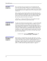
When a real-time display or printout is being transmitted to a printer or PC, a
new line of data is printed every 2 seconds. Every 25th line is a Column
Heading line. A column heading line is also printed any time a value in the
column heading line is changed. A real-time printout is shown in Figure 21 on
page 101.
Note:
If the data output stops transmitting, turn the power off and back on
again, or, if the monitor is connected to a PC, send an XON (Ctrl-q) to
resume transmission.
Summary of Contents for OXIMAX N-595
Page 1: ......
Page 8: ...This page intentionally left blank...
Page 13: ...Introduction N 595 5 Figure 4 Trend Softkey Map...
Page 50: ...This page intentionally left blank...
Page 76: ...This page intentionally left blank...
Page 82: ...This page intentionally left blank...
Page 96: ...This page intentionally left blank...
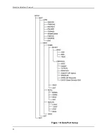
Page 98: ...Data Port Interface Protocol 90 Figure 19 Data Port Setup...
Page 116: ...This page intentionally left blank...
Page 125: ...Figure 27 Main PCB Schematic Diagram Sheet 1 of 13 117...
Page 126: ...Figure 28 Main PCB Schematic Diagram Sheet 2 of 13 119...
Page 127: ...Figure 29 Main PCB Schematic Diagram Sheet 3 of 13 121...
Page 128: ...Figure 30 Main PCB Schematic Diagram Sheet 4 of 13 123...
Page 129: ...Figure 31 Main PCB Schematic Diagram Sheet 5 of 13 125...
Page 130: ...Figure 32 Main PCB Schematic Diagram Sheet 6 of 13 127...
Page 131: ...Figure 33 Main PCB Schematic Diagram Sheet 7 of 13 129...
Page 132: ...Figure 34 Main PCB Schematic Diagram Sheet 8 of 13 131...
Page 133: ...Figure 35 Main PCB Schematic Diagram Sheet 9 of 13 133...
Page 134: ...Figure 36 Main PCB Schematic Diagram Sheet 10 of 13 135...
Page 135: ...Figure 37 Main PCB Schematic Diagram Sheet 11 of 13 137...
Page 136: ...Figure 38 Main PCB Schematic Diagram Sheet 12 of 13 139...
Page 137: ...Figure 39 Main PCB Schematic Diagram Sheet 13 of 13 141...
Page 138: ...Figure 40 Main PCB Assembly Drawing Front View 143...
Page 141: ...Figure 43 Linear Power Supply Assembly Drawing 149 AC FERRITE DC FERRITE...


