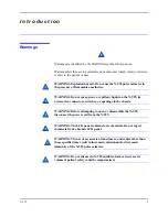
Introduction
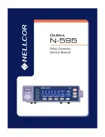
N-595
3
Intra-hospital transport includes transport of a patient within the
hospital or hospital-type facility.
Home Care use is defined as managed/used by a lay person (parent or
other similar non-critical caregiver) in the home environment.
Use with any particular patient requires the selection of an
appropriate oxygen transducer as described in this Operator's Manual.
Motion performance claims are applicable to models
MAX-A, MAX-AL, MAX-P, MAX-N, and MAX-I Nellcor
O
XI
M
AX
TM
oximetry sensors.
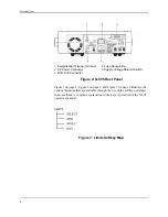
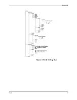
Through the use of the four softkeys, the operator can access trend
information, select an alarm limit to be changed, choose the language to be
used, adjust the internal time clock, and change communications protocol.
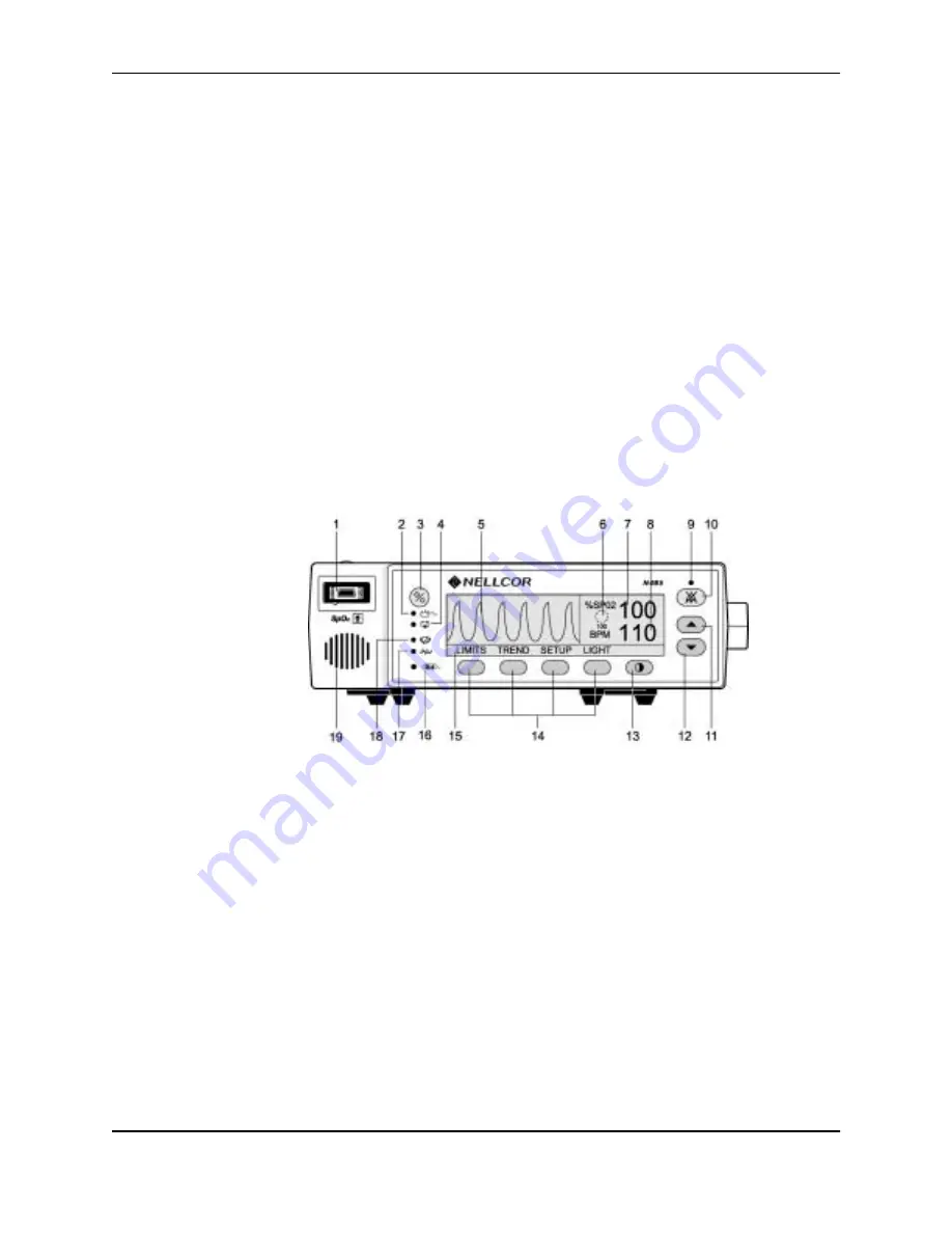
The N-595 can operate on AC power or on an internal battery. The controls
and indicators for the N-595 are illustrated and identified in Figure 1 on
page 3 and Figure 2 on page 4.
1. SpO
2
Sensor Port
11. ADJUST UP Button
2. AC Power Indicator
12. ADJUST DOWN Button
3. POWER ON/OFF Button
13. CONTRAST Button
4. Low Battery Indicator
14. Softkeys
5. Waveform Display
15. Menu Bar
6.
SatSeconds
TM
Timer
16. Trend In-Sensor Indicator
7. %SpO
2
Display
17. Motion Indicator
8. Pulse Rate Display
18. Pulse Search Indicator
9. Alarm Silence Display
19. Speaker
10. ALARM SILENCE Button
Figure 1: N-595 Front Panel
Summary of Contents for OXIMAX N-595
Page 1: ......
Page 8: ...This page intentionally left blank...
Page 13: ...Introduction N 595 5 Figure 4 Trend Softkey Map...
Page 50: ...This page intentionally left blank...
Page 76: ...This page intentionally left blank...
Page 82: ...This page intentionally left blank...
Page 96: ...This page intentionally left blank...
Page 98: ...Data Port Interface Protocol 90 Figure 19 Data Port Setup...
Page 116: ...This page intentionally left blank...
Page 125: ...Figure 27 Main PCB Schematic Diagram Sheet 1 of 13 117...
Page 126: ...Figure 28 Main PCB Schematic Diagram Sheet 2 of 13 119...
Page 127: ...Figure 29 Main PCB Schematic Diagram Sheet 3 of 13 121...
Page 128: ...Figure 30 Main PCB Schematic Diagram Sheet 4 of 13 123...
Page 129: ...Figure 31 Main PCB Schematic Diagram Sheet 5 of 13 125...
Page 130: ...Figure 32 Main PCB Schematic Diagram Sheet 6 of 13 127...
Page 131: ...Figure 33 Main PCB Schematic Diagram Sheet 7 of 13 129...
Page 132: ...Figure 34 Main PCB Schematic Diagram Sheet 8 of 13 131...
Page 133: ...Figure 35 Main PCB Schematic Diagram Sheet 9 of 13 133...
Page 134: ...Figure 36 Main PCB Schematic Diagram Sheet 10 of 13 135...
Page 135: ...Figure 37 Main PCB Schematic Diagram Sheet 11 of 13 137...
Page 136: ...Figure 38 Main PCB Schematic Diagram Sheet 12 of 13 139...
Page 137: ...Figure 39 Main PCB Schematic Diagram Sheet 13 of 13 141...
Page 138: ...Figure 40 Main PCB Assembly Drawing Front View 143...
Page 141: ...Figure 43 Linear Power Supply Assembly Drawing 149 AC FERRITE DC FERRITE...

