Routine Maintenance
8
2. Perform the electrical safety tests detailed in
Safety Tests
on page 28. If
the unit fails these electrical safety tests, refer to
Troubleshooting
on
3. Inspect the fuses for proper value and rating (F1 & F2 = 0.5 amp, 250
volts).
Battery
Nellcor recommends replacing the instrument's battery every 2 years. When
the N-595 is going to be stored for 3 months or more, remove the battery prior
to storage. To replace or remove the battery, refer to
Disassembly Guide
on
If the N-595 has been stored for more than 30 days, charge the battery as
described in
Battery Charge
on page 10. A fully discharged battery requires
14 hours with the monitor turned off, or 18 hours if it is in use, to receive a
full charge. The battery is being charged whenever the instrument is plugged
into AC.
Note:
If power stored in the battery is too low, the unit will not operate even
when plugged into AC. If this occurs, leave the unit plugged in to
allow the battery to charge as described in
Battery Charge
on
page 10. After approximately 10 minutes, the battery should have
enough charge to allow the unit to operate on AC.
Summary of Contents for OXIMAX N-595
Page 1: ......
Page 8: ...This page intentionally left blank...
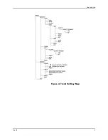
Page 13: ...Introduction N 595 5 Figure 4 Trend Softkey Map...
Page 50: ...This page intentionally left blank...
Page 76: ...This page intentionally left blank...
Page 82: ...This page intentionally left blank...
Page 96: ...This page intentionally left blank...
Page 98: ...Data Port Interface Protocol 90 Figure 19 Data Port Setup...
Page 116: ...This page intentionally left blank...
Page 125: ...Figure 27 Main PCB Schematic Diagram Sheet 1 of 13 117...
Page 126: ...Figure 28 Main PCB Schematic Diagram Sheet 2 of 13 119...
Page 127: ...Figure 29 Main PCB Schematic Diagram Sheet 3 of 13 121...
Page 128: ...Figure 30 Main PCB Schematic Diagram Sheet 4 of 13 123...
Page 129: ...Figure 31 Main PCB Schematic Diagram Sheet 5 of 13 125...
Page 130: ...Figure 32 Main PCB Schematic Diagram Sheet 6 of 13 127...
Page 131: ...Figure 33 Main PCB Schematic Diagram Sheet 7 of 13 129...
Page 132: ...Figure 34 Main PCB Schematic Diagram Sheet 8 of 13 131...
Page 133: ...Figure 35 Main PCB Schematic Diagram Sheet 9 of 13 133...
Page 134: ...Figure 36 Main PCB Schematic Diagram Sheet 10 of 13 135...
Page 135: ...Figure 37 Main PCB Schematic Diagram Sheet 11 of 13 137...
Page 136: ...Figure 38 Main PCB Schematic Diagram Sheet 12 of 13 139...
Page 137: ...Figure 39 Main PCB Schematic Diagram Sheet 13 of 13 141...
Page 138: ...Figure 40 Main PCB Assembly Drawing Front View 143...
Page 141: ...Figure 43 Linear Power Supply Assembly Drawing 149 AC FERRITE DC FERRITE...

