N-595
9
P e r f o r m a n c e V e r i f i c a t i o n
Introduction
This section discusses the tests used to verify performance following repairs
or during routine maintenance. All tests can be performed without removing
the N-595 cover. All tests except the battery charge and battery performance
tests must be performed as the last operation before the monitor is returned to
the user.
If the N-595 fails to perform as specified in any test, repairs must be made to
correct the problem before the monitor is returned to the user.
Equipment
Needed
Performance
Tests
The battery charge procedure should be performed before monitor repairs
whenever possible.
Note:
This section is written using Nellcor factory-set defaults. If your
institution has preconfigured custom defaults, those values will be
displayed. Factory defaults can be restored (see
Reset Softkey
,
Table 1: Equipment Needed
Equipment
Description
Digital Multimeter (DMM)
Fluke Model 87 or equivalent
Durasensor
®
oxygen transducer
DS-100A
O
XI
M
AX
oxygen transducer
MAX-A
Safety Analyzer
Must meet current AAMI ESI/1993 & IEC
60601-1/1998 specifications
Pulse oximetry cable
DOC-10
Data interface cable
EIA-232 cable (optional)
Stopwatch
Manual or electronic
SRC-MAX Tester
Provides testing for DigiCal compatible
Monitors
Summary of Contents for OXIMAX N-595
Page 1: ......
Page 8: ...This page intentionally left blank...
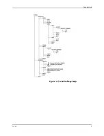
Page 13: ...Introduction N 595 5 Figure 4 Trend Softkey Map...
Page 50: ...This page intentionally left blank...
Page 76: ...This page intentionally left blank...
Page 82: ...This page intentionally left blank...
Page 96: ...This page intentionally left blank...
Page 98: ...Data Port Interface Protocol 90 Figure 19 Data Port Setup...
Page 116: ...This page intentionally left blank...
Page 125: ...Figure 27 Main PCB Schematic Diagram Sheet 1 of 13 117...
Page 126: ...Figure 28 Main PCB Schematic Diagram Sheet 2 of 13 119...
Page 127: ...Figure 29 Main PCB Schematic Diagram Sheet 3 of 13 121...
Page 128: ...Figure 30 Main PCB Schematic Diagram Sheet 4 of 13 123...
Page 129: ...Figure 31 Main PCB Schematic Diagram Sheet 5 of 13 125...
Page 130: ...Figure 32 Main PCB Schematic Diagram Sheet 6 of 13 127...
Page 131: ...Figure 33 Main PCB Schematic Diagram Sheet 7 of 13 129...
Page 132: ...Figure 34 Main PCB Schematic Diagram Sheet 8 of 13 131...
Page 133: ...Figure 35 Main PCB Schematic Diagram Sheet 9 of 13 133...
Page 134: ...Figure 36 Main PCB Schematic Diagram Sheet 10 of 13 135...
Page 135: ...Figure 37 Main PCB Schematic Diagram Sheet 11 of 13 137...
Page 136: ...Figure 38 Main PCB Schematic Diagram Sheet 12 of 13 139...
Page 137: ...Figure 39 Main PCB Schematic Diagram Sheet 13 of 13 141...
Page 138: ...Figure 40 Main PCB Assembly Drawing Front View 143...
Page 141: ...Figure 43 Linear Power Supply Assembly Drawing 149 AC FERRITE DC FERRITE...

