N-595
29
P o w e r - O n S e t t i n g s a n d S e r v i c e
F u n c t i o n s
Introduction
This section discusses how to reconfigure power-on default values and access
the service functions.
Power-On
Settings
The following paragraphs describe how to change power-on default settings.
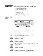
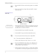
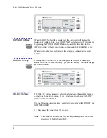
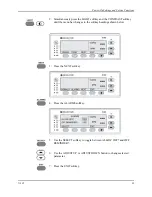
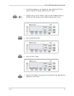
By using softkeys as shown in Figure 1 on page 3, the user can change alarm
limits, the type of display, baud rate, time and date, and trends to view.
Some values cannot be saved as power-on default values. An SpO
2
lower
alarm limit less than 80 will not be saved as a power-on default. Audible
Alarm Off will not be accepted as a power-on default. An attempt to save
either of these values as default will result in an invalid tone. These limits can
be adjusted lower for the current patient, but they will be lost when the
instrument is turned off.
A decimal point is added to the right of a display when the alarm limit for that
display has been changed to a value that is not a power-on default value. If the
new value is saved as a power-on default value, the decimal point will be
removed. By using the service functions, changes can be saved as power-on
default values.
Factory Default
Settings
Factory default settings are divided into two groups, adult and neonate.
Default settings may be changed to institutional default setting , refer to
Setting Institutional Defaults (Sample)
Neonate Default
Settings
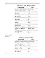
Table 2: Neonate Alarm Limit Factory Defaults
Monitoring Mode
Setting
Note: Bold entries are different than adult default settings.
%SpO
2
Lower Alarm Limit
80%
%SpO
2
Upper Alarm Limit
95%
Alarm Silence Duration
60 seconds
Summary of Contents for OXIMAX N-595
Page 1: ......
Page 8: ...This page intentionally left blank...
Page 13: ...Introduction N 595 5 Figure 4 Trend Softkey Map...
Page 50: ...This page intentionally left blank...
Page 76: ...This page intentionally left blank...
Page 82: ...This page intentionally left blank...
Page 96: ...This page intentionally left blank...
Page 98: ...Data Port Interface Protocol 90 Figure 19 Data Port Setup...
Page 116: ...This page intentionally left blank...
Page 125: ...Figure 27 Main PCB Schematic Diagram Sheet 1 of 13 117...
Page 126: ...Figure 28 Main PCB Schematic Diagram Sheet 2 of 13 119...
Page 127: ...Figure 29 Main PCB Schematic Diagram Sheet 3 of 13 121...
Page 128: ...Figure 30 Main PCB Schematic Diagram Sheet 4 of 13 123...
Page 129: ...Figure 31 Main PCB Schematic Diagram Sheet 5 of 13 125...
Page 130: ...Figure 32 Main PCB Schematic Diagram Sheet 6 of 13 127...
Page 131: ...Figure 33 Main PCB Schematic Diagram Sheet 7 of 13 129...
Page 132: ...Figure 34 Main PCB Schematic Diagram Sheet 8 of 13 131...
Page 133: ...Figure 35 Main PCB Schematic Diagram Sheet 9 of 13 133...
Page 134: ...Figure 36 Main PCB Schematic Diagram Sheet 10 of 13 135...
Page 135: ...Figure 37 Main PCB Schematic Diagram Sheet 11 of 13 137...
Page 136: ...Figure 38 Main PCB Schematic Diagram Sheet 12 of 13 139...
Page 137: ...Figure 39 Main PCB Schematic Diagram Sheet 13 of 13 141...
Page 138: ...Figure 40 Main PCB Assembly Drawing Front View 143...
Page 141: ...Figure 43 Linear Power Supply Assembly Drawing 149 AC FERRITE DC FERRITE...

