N-595
43
T r o u b l e s h o o t i n g
Introduction
This section explains how to troubleshoot the N-595 if problems arise. Tables
list possible monitor difficulties, along with probable causes, and
recommended actions to correct the difficulty.
How To Use
This Section
Use this section in conjunction with
Performance Verification
on page 9, and
Spare Parts
on page 69. To remove and replace a part you suspect is
defective, follow the instructions in
Disassembly Guide
on page 51. The
circuit analysis section in the
Technical Discussion
on page 109, offers
information on how the monitor functions.
Who Should
Perform
Repairs
Only qualified service personnel should open the monitor housing, remove
and replace components, or make adjustments. If your medical facility does
not have qualified service personnel, contact Nellcor’s Technical Services or
your local Nellcor representative.
Troubleshooting
Guide
Problems with the N-595 are categorized in Table 4 on page 43. Refer to the
paragraph indicated for further troubleshooting instructions.
Note:
Taking the recommended actions discussed in this section will correct
the majority of problems you may encounter. However, problems not
covered here can be resolved by calling Nellcor’s Technical Services
or your local Nellcor representative.
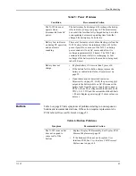
Table 4: Problem Categories
Problem Area
Refer To
1. Power
•
No power-up on AC and/or DC
•
Fails power-on self-test
•
Powers down without apparent cause
Power
2. Buttons
•
monitor does not respond properly to
buttons being pressed
Buttons
Summary of Contents for OXIMAX N-595
Page 1: ......
Page 8: ...This page intentionally left blank...
Page 13: ...Introduction N 595 5 Figure 4 Trend Softkey Map...
Page 50: ...This page intentionally left blank...
Page 76: ...This page intentionally left blank...
Page 82: ...This page intentionally left blank...
Page 96: ...This page intentionally left blank...
Page 98: ...Data Port Interface Protocol 90 Figure 19 Data Port Setup...
Page 116: ...This page intentionally left blank...
Page 125: ...Figure 27 Main PCB Schematic Diagram Sheet 1 of 13 117...
Page 126: ...Figure 28 Main PCB Schematic Diagram Sheet 2 of 13 119...
Page 127: ...Figure 29 Main PCB Schematic Diagram Sheet 3 of 13 121...
Page 128: ...Figure 30 Main PCB Schematic Diagram Sheet 4 of 13 123...
Page 129: ...Figure 31 Main PCB Schematic Diagram Sheet 5 of 13 125...
Page 130: ...Figure 32 Main PCB Schematic Diagram Sheet 6 of 13 127...
Page 131: ...Figure 33 Main PCB Schematic Diagram Sheet 7 of 13 129...
Page 132: ...Figure 34 Main PCB Schematic Diagram Sheet 8 of 13 131...
Page 133: ...Figure 35 Main PCB Schematic Diagram Sheet 9 of 13 133...
Page 134: ...Figure 36 Main PCB Schematic Diagram Sheet 10 of 13 135...
Page 135: ...Figure 37 Main PCB Schematic Diagram Sheet 11 of 13 137...
Page 136: ...Figure 38 Main PCB Schematic Diagram Sheet 12 of 13 139...
Page 137: ...Figure 39 Main PCB Schematic Diagram Sheet 13 of 13 141...
Page 138: ...Figure 40 Main PCB Assembly Drawing Front View 143...
Page 141: ...Figure 43 Linear Power Supply Assembly Drawing 149 AC FERRITE DC FERRITE...


