Troubleshooting
44
All of the problem areas in Table 4 on page 43 are discussed in the following
paragraphs.
Power
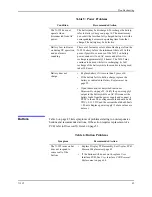
Power problems are related to AC and/or DC. Table 5 on page 44 lists
recommended actions to power problems.
3. Display/Alarms
•
Display does not respond properly
•
Alarms and other tones do not sound
properly or are generated without apparent
cause
Display/Alarms
on page 46
4. Operational Performance
•
Displays appear to be operational, but
monitor shows no readings
•
Suspect readings
Operating Performance
on
5. Data Port
•
N-595 data port not functioning properly
Data Port
Table 4: Problem Categories
Problem Area
Refer To
Table 5: Power Problems
Condition
Recommended Action
Battery Low indicator
lights steadily while
N-595 is connected to
AC and battery is not
discharged.
• Ensure that the N-595 is plugged into an operational
AC outlet and the AC indicator is on.
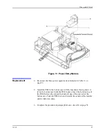
• Check the fuses. The fuses are located in the Power
Entry Module as indicated in
Fuse Replacement
on
page 52. Replace if necessary.
• Open the monitor as described in
monitor
Disassembly
on page 53. Verify the power supply's
output to the battery while on AC. Disconnect the
battery leads from the battery and connect a DVM to
them. The voltage measured should be 6.65 to 6.95
VDC and the current should be 320 to 480 mA.
Replace power supply if above values are not met.
• Check the harness connection from the bottom
enclosure to the User Interface PCB, as instructed in
User Interface PCB Removal/Replacement
on
page 64. If the connection is good, replace the User
Interface PCB.
Summary of Contents for OXIMAX N-595
Page 1: ......
Page 8: ...This page intentionally left blank...
Page 13: ...Introduction N 595 5 Figure 4 Trend Softkey Map...
Page 50: ...This page intentionally left blank...
Page 76: ...This page intentionally left blank...
Page 82: ...This page intentionally left blank...
Page 96: ...This page intentionally left blank...
Page 98: ...Data Port Interface Protocol 90 Figure 19 Data Port Setup...
Page 116: ...This page intentionally left blank...
Page 125: ...Figure 27 Main PCB Schematic Diagram Sheet 1 of 13 117...
Page 126: ...Figure 28 Main PCB Schematic Diagram Sheet 2 of 13 119...
Page 127: ...Figure 29 Main PCB Schematic Diagram Sheet 3 of 13 121...
Page 128: ...Figure 30 Main PCB Schematic Diagram Sheet 4 of 13 123...
Page 129: ...Figure 31 Main PCB Schematic Diagram Sheet 5 of 13 125...
Page 130: ...Figure 32 Main PCB Schematic Diagram Sheet 6 of 13 127...
Page 131: ...Figure 33 Main PCB Schematic Diagram Sheet 7 of 13 129...
Page 132: ...Figure 34 Main PCB Schematic Diagram Sheet 8 of 13 131...
Page 133: ...Figure 35 Main PCB Schematic Diagram Sheet 9 of 13 133...
Page 134: ...Figure 36 Main PCB Schematic Diagram Sheet 10 of 13 135...
Page 135: ...Figure 37 Main PCB Schematic Diagram Sheet 11 of 13 137...
Page 136: ...Figure 38 Main PCB Schematic Diagram Sheet 12 of 13 139...
Page 137: ...Figure 39 Main PCB Schematic Diagram Sheet 13 of 13 141...
Page 138: ...Figure 40 Main PCB Assembly Drawing Front View 143...
Page 141: ...Figure 43 Linear Power Supply Assembly Drawing 149 AC FERRITE DC FERRITE...

