Troubleshooting
N-595
49
Other Messages
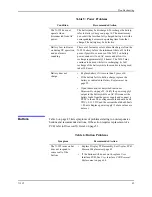
In addition to the error codes listed in Table 10 on page 49, the following
messages may be encountered:
Adjust Contrast Up,
Down
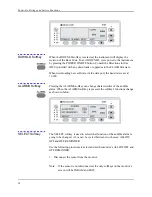
When the user attempts to adjust the contrast of the display by pressing or
pressing and holding the CONTRAST button.
Clock Settings Lost
If the N-595 detects that the real time clock has stopped running. This will
usually occur when both battery and AC power are lost.
Data In Sensor
When a sensor containing data is connected to the N-595.
Data Type: Event/
SpO
2
When a blank sensor is connected to a monitor with Data Type set to SpO
2
.
Data Type: Event/
SpO
2
+BPM
When a blank sensor is connected to a monitor with Data Type set to
SpO
2
+ BPM.
Defaults Lost
If the N-595 detects that the power-on settings have been lost.
Delete Trend?
When the user attempts to delete trend data from memory by pressing the
DELETE softkey.
Invalid Blip Vol
When the user attempts to save current settings as power-on defaults and the
blip volume is 0.
Table 10: Error Code Problems
Error
Code
Meaning
Possible Solution or Problem
Identification
4
Dead battery
Refer to Table 5 on page 44.
80
Institutional parameter lost
User interface module: Institutional
EEPROM section CRC corrupt
81
Current settings lost
User interface module: current
EEPROM section CRC corrupt
82
Clock setting lost
Re-enter the date and time.
Summary of Contents for OXIMAX N-595
Page 1: ......
Page 8: ...This page intentionally left blank...
Page 13: ...Introduction N 595 5 Figure 4 Trend Softkey Map...
Page 50: ...This page intentionally left blank...
Page 76: ...This page intentionally left blank...
Page 82: ...This page intentionally left blank...
Page 96: ...This page intentionally left blank...
Page 98: ...Data Port Interface Protocol 90 Figure 19 Data Port Setup...
Page 116: ...This page intentionally left blank...
Page 125: ...Figure 27 Main PCB Schematic Diagram Sheet 1 of 13 117...
Page 126: ...Figure 28 Main PCB Schematic Diagram Sheet 2 of 13 119...
Page 127: ...Figure 29 Main PCB Schematic Diagram Sheet 3 of 13 121...
Page 128: ...Figure 30 Main PCB Schematic Diagram Sheet 4 of 13 123...
Page 129: ...Figure 31 Main PCB Schematic Diagram Sheet 5 of 13 125...
Page 130: ...Figure 32 Main PCB Schematic Diagram Sheet 6 of 13 127...
Page 131: ...Figure 33 Main PCB Schematic Diagram Sheet 7 of 13 129...
Page 132: ...Figure 34 Main PCB Schematic Diagram Sheet 8 of 13 131...
Page 133: ...Figure 35 Main PCB Schematic Diagram Sheet 9 of 13 133...
Page 134: ...Figure 36 Main PCB Schematic Diagram Sheet 10 of 13 135...
Page 135: ...Figure 37 Main PCB Schematic Diagram Sheet 11 of 13 137...
Page 136: ...Figure 38 Main PCB Schematic Diagram Sheet 12 of 13 139...
Page 137: ...Figure 39 Main PCB Schematic Diagram Sheet 13 of 13 141...
Page 138: ...Figure 40 Main PCB Assembly Drawing Front View 143...
Page 141: ...Figure 43 Linear Power Supply Assembly Drawing 149 AC FERRITE DC FERRITE...


