background image

Disassembly Guide

60

10. Install the seven screws in the Power Supply and tighten.

11. Connect the fan harness to J1 on the Power Supply.

12. Install the PEM in the bottom case with the fuse drawer facing down. A 

tab in the bottom case holds the PEM in place. Insert the bottom wing of 
the PEM between the tab and the internal edge of the sidewall of the 
bottom case. Push the PEM down and towards the outside of the monitor 
until it clicks into place.

13. Complete the replacement procedure in paragraph 

Monitor Assembly

 on 

page 54.

Cooling Fan 
Removal/
Replacement

Removal

1. Complete the procedure in paragraphs 

Prior to Disassembly

 on page 52, 

and 

Monitor Disassembly

 on page 53.

2. Disconnect the fan wire harness from J1 on the Power Supply PCB (see 

Figure 13 on page 61).

3. Lift the cooling fan from the slots in the bottom case.

Summary of Contents for OXIMAX N-595

Page 1: ......

Page 2: ...ur local representative Purchase of this instrument confers no express or implied license under any Nellcor Puritan Bennett patent to use the instrument with any sensor that is not manufactured or lic...

Page 3: ...y Tests 28 Power On Settings and Service Functions 29 Introduction 29 Power On Settings 29 Factory Default Settings 29 Neonate Default Settings 29 Adult Default Settings 30 Service Functions 31 Access...

Page 4: ...er Removal Replacement 66 Removal 66 Replacement 67 Spare Parts 69 Introduction 69 Obtaining Replacement Parts 69 Parts List 69 Packing for Shipment 71 Introduction 71 Returning the N 595 71 General I...

Page 5: ...og Option 4 100 Exit Interactive Mode Option 5 100 Using Data on the PC 100 Real Time Printout 100 Column Heading 101 Patient Data and Operating Status 103 Trend Data Printout ASCII Mode 104 Trend Pri...

Page 6: ...11 Power Entry Module 57 Figure 12 Power Supply 59 Figure 13 Cooling Fan 61 Figure 14 Display PCB 63 Figure 15 User Interface PCB 65 Figure 16 Alarm Speaker 67 Figure 17 Exploded View 70 Figure 18 Pac...

Page 7: ...Table 9 Data Port Problems 48 Table 10 Error Code Problems 49 Table 11 Power Supply Lead Connections 59 Table 12 Parts List 69 Table 13 Electromagnetic Emissions IEC 60601 1 2 80 Table 14 Electromagn...

Page 8: ...This page intentionally left blank...

Page 9: ...uid on the N 595 its accessories connectors switches or openings in the chassis WARNING Before attempting to open or disassemble the N 595 disconnect the power cord from the N 595 WARNING The LCD pane...

Page 10: ...Nellcor model N 595 pulse oximeter Only qualified service personnel should service this product Before servicing the N 595 read the operator s manual carefully for a thorough understanding of safe op...

Page 11: ...r can access trend information select an alarm limit to be changed choose the language to be used adjust the internal time clock and change communications protocol The N 595 can operate on AC power or...

Page 12: ...Data Port Connector Figure 2 N 595 Rear Panel Figure 3 on page 4 Figure 4 on page 5 and Figure 5 on page 6 illustrate the various functions that are available through the use of the softkeys and how...

Page 13: ...Introduction N 595 5 Figure 4 Trend Softkey Map...

Page 14: ...operator s manual To understand the various Nellcor approved sensors that work with the monitor refer to the individual sensor s directions for use The latest version of the operator s manual and the...

Page 15: ...sensor Each sensor model has cleaning instructions specific to that sensor Periodic Safety Checks The N 595 requires no routine service or calibration other than changing the battery at least every 2...

Page 16: ...to Disassembly Guide on page 51 If the N 595 has been stored for more than 30 days charge the battery as described in Battery Charge on page 10 A fully discharged battery requires 14 hours with the m...

Page 17: ...Needed Performance Tests The battery charge procedure should be performed before monitor repairs whenever possible Note This section is written using Nellcor factory set defaults If your institution h...

Page 18: ...imit Ranges page 11 Power On Self Test 1 Connect the monitor to an AC power source 2 Verify that the monitor is off and that the AC Power Battery Charging indicator is lit 3 Do not connect any cables...

Page 19: ...tion is taken within the time out the monitor automatically returns to the monitoring display Note The descriptions that follow are based on the assumption that Pleth view is the view that has been se...

Page 20: ...ve been changed from factory default values 4 Press the SELECT softkey Verify that the monitor emits a single beep and the box moves to the SpO2 lower alarm limit of 85 or your institutional default s...

Page 21: ...t 12 Press the EXIT softkey 13 Press the LIMITS softkey 14 Press the SELECT softkey four times Verify that the pulse rate lower alarm limit display indicates an alarm limit of 40 and is boxed 15 Press...

Page 22: ...to turn the monitor back on 23 Press the LIMITS softkey Verify that the SpO2 upper alarm limit display is boxed and indicates an alarm limit of 100 24 Verify that the SpO2 lower alarm limit display i...

Page 23: ...on Battery Power page 20 Alarms and Alarm Silence 1 Sensor Port 1 Connect the DOC 10 monitor cable to the monitor sensor port 2 Connect the DS 100 sensor to the DOC 10 cable and yourself 3 Press the...

Page 24: ...display indicates SEC Continue to press the ALARM SILENCE button and press the ADJUST DOWN button until 60 is displayed in the SPO2 display 14 Press the ALARM SILENCE button 15 With the monitor s alar...

Page 25: ...default setting of 5 2 While still pressing the ALARM SILENCE button press the ADJUST DOWN button until an alarm volume setting of 1 is displayed Verify that the volume of the alarm has decreased but...

Page 26: ...ff 2 Connect the SRC MAX tester to the DOC 10 sensor cable 3 Connect the DOC 10 sensor cable to the monitor SpO2 connector 4 Turn on the monitor and wait for the monitor to complete POST Note The moni...

Page 27: ...ty between pins 7 and 15 This verifies the solid state Nurse Call function Analog Output 1 Data Port Connector 1 Connect the negative lead of a voltmeter to pin 10 and positive to pin 6 of the data po...

Page 28: ...key 13 Press the ANALOG softkey 14 Press the 0 VOLT softkey 15 Verify that the monitor s output voltage is 0 0 0 025 VDC 16 Leave the negative lead connected to pin 10 and verify 0 0 0 025 VDC on pins...

Page 29: ...re uses normal system components to test circuit operation A Nellcor OXIMAX oxygen transducer model MAX A is used to examine LED intensity control The red LED is used to verify intensity modulation ca...

Page 30: ...control of LED intensity 10 Press the POWER ON OFF button to turn the monitor off Operation with a Live Subject Patient monitoring involves connecting the sensor to a live subject for a qualitative t...

Page 31: ...unctional Tests These tests utilizes the pulse oximetry functional tester SRC MAX to verify the performance of the N 595 monitor All of these tests should be done in sequence 1 DOC 10 Cable Connector...

Page 32: ...e POWER ON OFF button 4 After the monitor completes POST the monitor will be in SpO2 alarm display an SpO2 of 75 Test pass criteria is 73 to 77 SpO2 display a pulse rate of 60 Test pass criteria is 57...

Page 33: ...E 200 LED will light 2 The monitor BPM will increase to 200 and stabilize at 200 BPM The test pass criteria is 197 to 203 BPM 3 The monitor will display 90 SpO2 200 BPM alarm low level modulation 4 Pr...

Page 34: ...button The SRC MAX MODULATION LED will light 2 The monitor waveform display will spike and stabilizes at a higher modulation level 3 The monitor will display 90 SpO2 60 BPM no alarm high level modula...

Page 35: ...n The SRC MAX Light Level LED will light 2 The monitor will waveform display will go flat and stabilizes at the low light level 3 The monitor will display 90 SpO2 60 BPM no alarm low level modulation...

Page 36: ...must comply with the applicable standard Ground Integrity see page 86 for test value Earth Leakage Current see page 86 for test values Enclosure Leakage Current see page 87 for test values Patient Ap...

Page 37: ...d tone These limits can be adjusted lower for the current patient but they will be lost when the instrument is turned off A decimal point is added to the right of a display when the alarm limit for th...

Page 38: ...beats per minute Pulse Rate Upper Alarm Limit 190 beats per minute SatSeconds Off Sensor Adjust Enabled Yes Trend Display SpO2 Table 2 Neonate Alarm Limit Factory Defaults Monitoring Mode Setting Not...

Page 39: ...the monitor 1 Turn on the N 595 by pressing the POWER ON OFF button 2 Wait for monitor power on self test to complete 3 Simultaneously press and hold the LIGHT softkey and the CONTRAST button until th...

Page 40: ...le connected only the PARAM and EXIT softkeys appear on the screen Figure 6 on page 33 can be used as a quick reference showing how to reach different softkey functions Items reached through the PARAM...

Page 41: ...oftkeys to display all of the options that are available at some levels of the menu Pressing the NEXT softkey allows you to view additional options available at a given menu level Param Softkey Menu W...

Page 42: ...off cycles until they are changed and saved again or until they are reset If NO is pressed the changed values will not be saved Note An invalid tone indicates that a parameter value cannot be saved as...

Page 43: ...of instrument delivering the information the software level type of printout and alarm parameters The second line lists the headings for the columns These lines are printed out every 25 lines or when...

Page 44: ...a along with the deleted trends can be retrieved from the instrument through an Instat printout The oldest deleted trend is Trend 01 on the Instat printout If a Trend 01 already exists in memory from...

Page 45: ...nted in the printout going from left to right is the instrument type N 595 software version level type of printout INFO CRC Cyclic Redundancy Check number and ratio of current operating time to total...

Page 46: ...et at 19 200 ALARMS Softkey Pressing the ALARMS softkey can change characteristics of the audible alarm When the ALARMS softkey is pressed the softkey s functions change as shown in below SELECT Softk...

Page 47: ...CONTRAST softkey until the menu bar changes to the softkey headings shown below 3 Press the NEXT softkey 4 Press the ALARMS softkey 5 Use the SELECT softkey to toggle between ALLOW OFF and OFF REMINDE...

Page 48: ...ts in the normal operation mode and you will set the institutional defaults in the monitor s service mode The following default values may be set Alarm Silence Duration 30 60 90 120 seconds Alarms All...

Page 49: ...or s manual for the procedures to set the values 3 Simultaneously press the LIGHT softkey and the CONTRAST button until the menu bar changes to the softkey headings shown below 4 Press the PARAM softk...

Page 50: ...This page intentionally left blank...

Page 51: ...the monitor housing remove and replace components or make adjustments If your medical facility does not have qualified service personnel contact Nellcor s Technical Services or your local Nellcor repr...

Page 52: ...n Recommended Action Battery Low indicator lights steadily while N 595 is connected to AC and battery is not discharged Ensure that the N 595 is plugged into an operational AC outlet and the AC indica...

Page 53: ...ximately 14 hours The N 595 may continue to be used while it is recharging A full recharge of the battery while the monitor is being used takes 18 hours Battery does not charge Replace battery if it i...

Page 54: ...t light Check the connection between the User Interface PCB and the Display PCB If the condition does not change replace the Display PCB See Display PCB Removal Replacement on page 62 If the condition...

Page 55: ...e PCB See User Interface PCB Removal Replacement on page 64 SpO2 or Pulse values change rapidly Pulse Amplitude indicator is erratic The sensor may be damp or may have been reused too many times Repla...

Page 56: ...ument off and back on again If the error code reappears record it and notify Nellcor Technical Services Department Table 9 Data Port Problems Symptom Recommended Action No printout is being received C...

Page 57: ...h Data Type set to SpO2 Data Type Event SpO2 BPM When a blank sensor is connected to a monitor with Data Type set to SpO2 BPM Defaults Lost If the N 595 detects that the power on settings have been lo...

Page 58: ...reset to factory defaults by pressing the RESET softkey on the Parameters menu the monitor displays the options YES and NO Save Defaults When the user attempts to save the current settings as the powe...

Page 59: ...ing within the unit Note Some spare parts have a business reply card attached When you receive these spare parts please fill out and return the card Replacement Level Supported The replacement level s...

Page 60: ...dure in paragraph Prior to Disassembly on page 52 2 Disconnect the power cord from the back of the monitor 3 Remove the fuse drawer from the power module by pressing down on the tab in the center and...

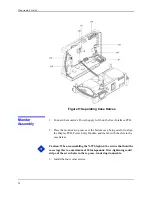
Page 61: ...n Observe ESD electrostatic discharge precautions when disassembling and reassembling the N 595 and when handling any of the components of the N 595 4 Separate the monitor s top case from the bottom c...

Page 62: ...case over the bottom case being careful to align the Display PCB Power Entry Module and the fan with the slots in the case halves Caution When reassembling the N 595 tighten the screws that hold the...

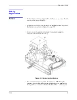
Page 63: ...attery out of the bottom case as shown in Figure 10 on page 55 3 Be sure to note the polarity of the leads Use needle nose pliers to disconnect the leads from the battery Figure 10 Removing the Batter...

Page 64: ...cket and grounding lead with the two screws 7 Complete the procedure in paragraph Monitor Assembly on page 54 8 Turn the monitor on and verify proper operation Power Entry Module PEM Removal Replaceme...

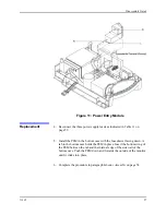
Page 65: ...EM in the bottom case with the fuse drawer facing down A tab in the bottom case holds the PEM in place Insert the bottom wing of the PEM between the tab and the internal edge of the sidewall of the bo...

Page 66: ...de of the case and lift up 3 Use needle nose pliers to disconnect the leads from the PEM see Figure 11 on page 57 4 Disconnect the fan wire harness from J1 on the Power Supply PCB see Figure 12 on pag...

Page 67: ...alling the Power Supply tighten the seven screws to a maximum of 4 inch pounds Over tightening could strip out the screw holes in the bottom case rendering it unusable Table 11 Power Supply Lead Conne...

Page 68: ...he internal edge of the sidewall of the bottom case Push the PEM down and towards the outside of the monitor until it clicks into place 13 Complete the replacement procedure in paragraph Monitor Assem...

Page 69: ...ect the cooling fan wire harness to J1 on the Power Supply PCB 5 Insert the cooling fan into the slots in the bottom case with the padded sides on the top and bottom and the fan s harness to the handl...

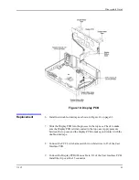
Page 70: ...2 and Monitor Disassembly page 53 2 Disconnect the CCFL harness from J5 of the User Interface PCB See Figure 14 on page 63 3 Use a small blade screwdriver to pry the clip from either edge of J13 then...

Page 71: ...op case Check to make sure the Display PCB is firmly seated in the top case Apply pressure between the top case and the display PCB to make good contact with the double sided tape 8 Connect the CCFL w...

Page 72: ...ge 63 3 Use a small blade screwdriver to pry the clip from either edge of J13 then disconnect the Display PCB ribbon cable from the connector 4 Disconnect the keypad ribbon cable from connector J17 on...

Page 73: ...ould strip out the screw holes in the top case rendering it unusable 8 Place the User Interface PCB in the top case 9 Install the five screws in the User Interface PCB 10 Lift up on the outer shell of...

Page 74: ...ce PCB Install the clip over the J13 connector 14 Complete the procedure in paragraph Monitor Assembly page 54 Alarm Speaker Removal Replacement Removal 1 Complete the procedures in paragraphs Prior t...

Page 75: ...ure 16 Alarm Speaker Replacement 4 Pull the holding clip back and insert the speaker into the top case 5 Connect speaker wire harness to J12 on the User Interface PCB 6 Complete the procedure in parag...

Page 76: ...This page intentionally left blank...

Page 77: ...rmation and replacement parts To obtain replacement parts contact Nellcor or your local Nellcor representative Refer to parts by the part names and part numbers Spare parts and accessories for the N 5...

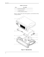
Page 78: ...17 on page 70 shows the N 595 expanded view with numbers relating to the spare parts list Figure 17 Exploded View Power Cord not shown Tilt Stand not shown GCX Mounting Kit not shown Table 12 Parts L...

Page 79: ...roof of delivery General Instructions Pack the monitor carefully Failure to follow the instructions in this section may result in loss or damage not covered by any applicable Nellcor warranty If the o...

Page 80: ...Packing for Shipment 72 Figure 18 Packing 2 Place in shipping carton and seal carton with packing tape 3 Label carton with shipping address return address and RGA number if applicable...

Page 81: ...ed cardboard shipping carton with a bursting strength of at least 200 pounds per square inch psi 3 Fill the bottom of the carton with at least 2 inches of packing material 4 Place the bagged unit on t...

Page 82: ...This page intentionally left blank...

Page 83: ...IMAX MAX A and MAX N sensors with the N 595 Neonate specifications are shown for OXIMAX MAX N sensors with the N 595 Saturation accuracy will vary by sensor type Refer to the Sensor Accuracy Grid 2 Ap...

Page 84: ...et for 224 bpm high light and low modulation Type Lead acid Voltage 6 Volts DC Recharge 14 hours with N 595 turned off 18 hours with N 595 operating Shelf Life 2 months new fully charged battery After...

Page 85: ...ng container Temperature 20 C to 70 C 4 F to 158 F Altitude Barometric Pressure 390 m to 4 572 m 1 280 ft to 15 000 ft 50 kPa to 106 kPa 31 3 in Hg to 14 in Hg Relative Humidity 15 to 95 non condensin...

Page 86: ...r label to indicate Type BF applied part IEC 60601 1 Symbol 2 of Table DII of Appendix D Equipotential lug symbol to indicate a potential equalization conductor IEC 60601 1 Symbol 9 of Table DI of App...

Page 87: ...1 sub clause 36 IEC EN 60601 1 2 second edition Radiated and conducted emissions EN 55011 Group 1 Class B Electrostatic discharge immunity EN 61000 4 2 level 3 table top equipment Quasi static electr...

Page 88: ...specified electromagnetic environment The customer and or user of the N 595 should assure that it is used in an electromagnetic environment as described below Emissions Test Compliance Electromagneti...

Page 89: ...s power quality should be that of a typical commercial and or hospital environment Surge IEC 61000 4 5 1 kV differential mode 2 kV common mode 1 kV differential mode 2 kV common mode Mains power quali...

Page 90: ...easured in the intended installation location to assure that it is sufficiently low Table 14 Electromagnetic Immunity IEC 60601 1 2 The N 595 is suitable for use in the specified electromagnetic envir...

Page 91: ...61000 4 6 3 Vrms 150 kHz to 80 MHz 3 V distance 1 2 Power 150 kHz to 80 MHz Note Field strengths from fixed transmitters such as base stations for radio cellular cordless telephones and land mobile ra...

Page 92: ...s Separation Distance in Meters Separation Distance in Meters 0 01 0 12 0 12 0 23 0 1 0 38 0 38 0 73 1 1 2 1 2 2 3 10 3 8 3 8 7 3 100 12 12 23 For transmitters rated at a maximum output power not list...

Page 93: ...m Non terminated cable RS 232 Analog 15 pin D 10 ft 3 m Oxinet hardwire cable 10 ft 3 m Printer cable RS 232 15 to 9 pin D 10 ft 3 m HP Agilent interface cable 3 3 ft 1 m GE Marquette interface cable...

Page 94: ...3 OXIMAXOxiCliq sensors P N I A 3 feet 0 91 m RF emissions CISPR 11 Class B Group 1 Harmonic emissions IEC 61000 3 2 Voltage fluctuations flicker emission IEC 61000 3 3 Electrostatic discharge ESD IEC...

Page 95: ...losed 500 A 100 A Open Open Closed 500 A 300 A Open Closed Open 500 A 300 A AC Line Polarity Neutral Line Power Line Ground Cable IEC 60601 1 AAMI ANSI Standard ES1 Normal Closed Closed 100 A 10 A Nor...

Page 96: ...This page intentionally left blank...

Page 97: ...SpO2 pulse rate and pulse amplitude are also provided by the data port A nurse call function is also available from the data port Each of these is discussed in more detail in the paragraphs that foll...

Page 98: ...Data Port Interface Protocol 90 Figure 19 Data Port Setup...

Page 99: ...by pressing the POWER ON OFF button 2 Press the SETUP softkey 3 Press the NEXT softkey 4 Press the NEXT softkey 5 Press the COMM softkey 6 Use the ADJUST UP and ADJUST DOWN buttons to select the desi...

Page 100: ...y pressing the POWER ON OFF button 2 Press the SETUP softkey 3 Press the NEXT softkey 4 Press the NEXT softkey 5 Press the COMM softkey 6 Press the SELECT softkey 7 Use the ADJUST UP and ADJUST DOWN b...

Page 101: ...Call available at pins 11 and 5 can be selected through the softkeys NORM sets the voltage to 5 VDC to 12 VDC and NORM sets the voltage to 5 VDC to 12 VDC when there is no audible alarm When an audibl...

Page 102: ...o adjust a recorder to the output of the instrument Selectable calibration signals are 1 0 VDC 0 0 VDC and Step For more information on the analog signals see Analog Output page 106 1 Turn on the N 59...

Page 103: ...e Agilent monitor only displays visual alarm indications for equipment interfaced through the Agilent VueLinkTM Aux Plus B interface module The N 595 monitor must be able to sound an audible alarm in...

Page 104: ...nnector for the N 595 and the applicable connector for the Marquette OctanetTM interface module cable Nellcor cable part number 902254 is recommended for this interface Corrupt data will be indicated...

Page 105: ...nt safety Note The parameters setup for the Datex Ohmeda bedside monitor interface may be saved as institutional default settings See Setting Industrial Defaults Sample page 40 Use care when performin...

Page 106: ...etal shell If rough handling or sharp bends in the cable is anticipated use a braided shield Communication With a PC Data can be sent from the N 595 to a PC by using a data cable with a Null modem con...

Page 107: ...ch includes software version CRC number and total operating time Set Date and Time Option 2 When the instrument is shipped from the factory the date and time are set to the time zone by the manufactur...

Page 108: ...fy that the communications format is compatible with the data port of the N 595 If the communications format is compatible real time data will begin to be displayed on the PC Capture the text to a fil...

Page 109: ...components The first two lines of the chart are the Column Headings shown below Every 25th line a Column Heading is printed A column heading is also printed whenever a value of the Column Heading is...

Page 110: ...are upgrade Alarm Limits The last data field in the top line indicates the upper and the lower alarm limits for SpO2 and for the pulse rate PR In the example above the lower alarm limit for SpO2 is 70...

Page 111: ...tes that 190 beats per minute is outside of the alarm limits indicated in the top row for pulse rate If no data for a parameter is available three dashes will be displayed in the printout Pulse Amplit...

Page 112: ...gs are displayed in 4 second intervals The values on each row are an average for the 4 second period At the end of the printout an Output Complete line indicates that the transmission was successful I...

Page 113: ...Figure 23 Monitor Trend Data Printout Graph Mode Figure 24 In Sensor Event Trend Data Printout Graph Mode Nurse Call An RS 232 Nurse Call signal pins 5 and 11 can be obtained by connecting to the dat...

Page 114: ...0 for pulse rate it equals 250 bpm and for plethysmographic waveform it equals 254 pulse amplitude units The voltage will decrease as the values for these parameters decrease If no data for a paramete...

Page 115: ...The stair step signal will start at 0 0 VDC and increase up to 1 0 VDC in 0 1 VDC increments Each increment will be held for 1 second Through use of the softkeys the 0 0 VDC 1 0 VDC or stair step sign...

Page 116: ...This page intentionally left blank...

Page 117: ...and that the volume of arterial blood in tissue and hence light absorption by that blood changes during the pulse i e plethysmography A pulse oximeter determines SpO2 by passing red and infrared light...

Page 118: ...turation oxygenated hemoglobin expressed as a percentage of the hemoglobin that can transport oxygen It does not detect significant amounts of dysfunctional hemoglobin such as carboxyhemoglobin or met...

Page 119: ...eased micro processing power with advanced mathematical algorithms Oxismart XL advanced signal processing allows the N 595 to read through challenging motion conditions to deliver accurate saturation...

Page 120: ...technology including the N 595 use calibration data contained in the sensor in calculating the patient s SpO2 By having the calibration in the sensor rather than the pulse oximeter the published accu...

Page 121: ...is electrically isolated to reduce capacitive coupling to earth ground and improve the FE 102 s ability to read difficult patients The SIP SOP is isolated as mandated by regulations for patient safet...

Page 122: ...n and storage Static random access memory RAM and FLASH read only memory ROM are provided for the microprocessor on the PCB Two systems pulse oximeter integrated circuits ICs on the main PCB Vcc 5 vol...

Page 123: ...on various N 595 and sensor conditions The N 595 contains a speaker for audio output The static RAM and the RTC for the microprocessor are powered whenever the N 595 has power either AC power or batt...

Page 124: ...Technical Discussion 116 Figure 42 Linear Power Supply Schematic Diagram Figure 43 Linear Power Supply Assembly Drawing...

Page 125: ...Figure 27 Main PCB Schematic Diagram Sheet 1 of 13 117...

Page 126: ...Figure 28 Main PCB Schematic Diagram Sheet 2 of 13 119...

Page 127: ...Figure 29 Main PCB Schematic Diagram Sheet 3 of 13 121...

Page 128: ...Figure 30 Main PCB Schematic Diagram Sheet 4 of 13 123...

Page 129: ...Figure 31 Main PCB Schematic Diagram Sheet 5 of 13 125...

Page 130: ...Figure 32 Main PCB Schematic Diagram Sheet 6 of 13 127...

Page 131: ...Figure 33 Main PCB Schematic Diagram Sheet 7 of 13 129...

Page 132: ...Figure 34 Main PCB Schematic Diagram Sheet 8 of 13 131...

Page 133: ...Figure 35 Main PCB Schematic Diagram Sheet 9 of 13 133...

Page 134: ...Figure 36 Main PCB Schematic Diagram Sheet 10 of 13 135...

Page 135: ...Figure 37 Main PCB Schematic Diagram Sheet 11 of 13 137...

Page 136: ...Figure 38 Main PCB Schematic Diagram Sheet 12 of 13 139...

Page 137: ...Figure 39 Main PCB Schematic Diagram Sheet 13 of 13 141...

Page 138: ...Figure 40 Main PCB Assembly Drawing Front View 143...

Page 139: ...AT34 C11 R127 AT174 AT174 C166 AT120 AT356 L5 C99 R180 AT181 AT181 AT380 AT750 C145 C32 R132 C180 C84 AT578 R189 AT476 AT668 AT231 C39 AT205 R48 C75 AT17 AT8 AT510 D16 C106 AT456 C148 AT649 Q1 L15 R42...

Page 140: ...C FAC MAIN_DC MAIN_DC AC AC 0 01U C8 DT1 600V TH I3 W5 W2 W6 W9 W7 W1 E BATT_CHK FAN_CTRL 0 1U C10 100M TH R2 1 4W I2 TP1 1 2W R1 390K TH LINE NEUT_IN LINE_IN EPS2PC3 SW1 TH 6 5 4 3 2 1 1 2 3 4 5 6 SW...

Page 141: ...Figure 43 Linear Power Supply Assembly Drawing 149 AC FERRITE DC FERRITE...

Page 142: ...harge 10 Battery in Use 104 Battery Replacement 55 Block Diagram Theory 113 BU 104 Button Problems 45 C Cables IEC 60601 1 2 85 Calculated Saturation 110 Calibration 7 Cautions 2 Cleaning 7 Communicat...

Page 143: ...F Factory Default Settings 29 Fractional Saturation 110 Front Panel 3 Functional Checks 7 Functional Saturation 110 functional saturation 110 Fuse Replacement 52 G Graph Mode 105 H Hospital Type Envir...

Page 144: ...OXIMAX Technology 111 OxiMAX Technology 3 Oximetry Overview 109 P Packing for Shipment 71 Param Softkey 33 Parts List 69 Patient Applied Risk Current 28 Patient Isolation Risk Current 28 Performance T...

Page 145: ...y 38 Sensor Disconnect 104 Sensor Disconnected 50 Sensor Power Dissipation 77 Service Function Menu 33 Service Functions 31 Service Functions Accessing 31 Setting Institutional Defaults 40 Setup Softk...

Page 146: ...Index N 595 155 Trend Softkey Map 5 Troubleshooting Guide 43 U User Interface PCB Replacement 64 Using Data on the PC 100 W Warnings Definition 1 Who Should Perform Repairs 43...

Page 147: ...Hacienda Drive Pleasanton CA 94588 USA Telephone Toll Free 1 800 NELLCOR Tyco Heathcare UK LTD 154 Fareham Road Gosport PO13 0AS U K Telephone 44 1329 224000 2001 Nellcor Puritan Bennett Inc All righ...

Reviews: