Specifications
N-595
81
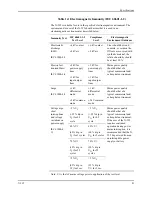
Table 14: Electromagnetic Immunity (IEC 60601-1-2)
The N-595 is suitable for use in the specified electromagnetic environment. The
customer and/or user of the N-595 should assure that it is used in an
electromagnetic environment as described below.
Immunity Test
IEC 60601-1-2
Test Level
Compliance
Level
Electromagnetic
Environment Guidance
Electrostatic
discharge
(ESD)
IEC 61000-4-2
±6 kV contact
±8 kV air
±6 kV contact
±8 kV air
Floor should be wood,
concrete, or ceramic tile.
If floors are covered with
synthetic material, the
relative humidity should
be at least 30 %.
Electric fast
transient/burst
IEC 61000-4-4
±2 kV for
power supply
lines
±1 kV for
input/output
lines
±2 kV for
power supply
lines
±1 kV for
input/output
lines
Mains power quality
should be that of a
typical commercial and/
or hospital environment
Surge
IEC 61000-4-5
±1 kV
differential
mode
±2 kV common
mode
±1 kV
differential
mode
±2 kV common
mode
Mains power quality
should be that of a
typical commercial and/
or hospital environment
Voltage dips,
short
interruptions
and voltage
variations on
power supply
IEC 61000-4-
11
<5 % U
T
(>95 % dip in
U
T
) for 0.5
cycle
<5 % U
T
(>95 % dip in
U
T)
for 0.5
cycle
Mains power quality
should be that of a
typical commercial and/
or hospital environment.
If the user of the N-595
requires continued
operation during power
mains interruption, it is
recommended that the N-
595 be powered from an
uninterruptible power
supply or battery.
40 % U
T
(60 % dip in
U
T
) for 5 cycles
40 % U
T
(60 % dip in
U
T)
for 5 cycles
70 % U
T
(30 % dip in
U
T
) for 25
cycles
70 % U
T
(30 % dip in
U
T)
for 25
cycles
<5 % U
T
(95 % dip in
U
T
) for 5 sec.
<5 % U
T
(95 % dip in
U
T)
for 5 sec.
Note: U
T
is the AC mains voltage prior to application of the test level.
Summary of Contents for OXIMAX N-595
Page 1: ......
Page 8: ...This page intentionally left blank...
Page 13: ...Introduction N 595 5 Figure 4 Trend Softkey Map...
Page 50: ...This page intentionally left blank...
Page 76: ...This page intentionally left blank...
Page 82: ...This page intentionally left blank...
Page 96: ...This page intentionally left blank...
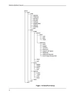
Page 98: ...Data Port Interface Protocol 90 Figure 19 Data Port Setup...
Page 116: ...This page intentionally left blank...
Page 125: ...Figure 27 Main PCB Schematic Diagram Sheet 1 of 13 117...
Page 126: ...Figure 28 Main PCB Schematic Diagram Sheet 2 of 13 119...
Page 127: ...Figure 29 Main PCB Schematic Diagram Sheet 3 of 13 121...
Page 128: ...Figure 30 Main PCB Schematic Diagram Sheet 4 of 13 123...
Page 129: ...Figure 31 Main PCB Schematic Diagram Sheet 5 of 13 125...
Page 130: ...Figure 32 Main PCB Schematic Diagram Sheet 6 of 13 127...
Page 131: ...Figure 33 Main PCB Schematic Diagram Sheet 7 of 13 129...
Page 132: ...Figure 34 Main PCB Schematic Diagram Sheet 8 of 13 131...
Page 133: ...Figure 35 Main PCB Schematic Diagram Sheet 9 of 13 133...
Page 134: ...Figure 36 Main PCB Schematic Diagram Sheet 10 of 13 135...
Page 135: ...Figure 37 Main PCB Schematic Diagram Sheet 11 of 13 137...
Page 136: ...Figure 38 Main PCB Schematic Diagram Sheet 12 of 13 139...
Page 137: ...Figure 39 Main PCB Schematic Diagram Sheet 13 of 13 141...
Page 138: ...Figure 40 Main PCB Assembly Drawing Front View 143...
Page 141: ...Figure 43 Linear Power Supply Assembly Drawing 149 AC FERRITE DC FERRITE...


