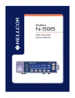
N-595
7
R o u t i n e M a i n t e n a n c e
Cleaning
WARNING: Do not spray, pour, or spill any liquid on the N-595, its
accessories, connectors, switches, or openings in the chassis.
For
surface-cleaning
and
disinfecting
follow your institution's procedures or:
•
The N-595 may be
surface-cleaned
by using a soft cloth dampened
with either a commercial, nonabrasive cleaner or a solution of 70%
alcohol in water, and lightly wiping the surfaces of the monitor.
•
The N-595 may be
disinfected
using a soft cloth saturated with a 10%
solution of chlorine bleach in tap water.
Before attempting to clean an SpO
2
sensor, read the directions for use
enclosed with the sensor. Each sensor model has cleaning instructions specific
to that sensor.
Periodic Safety
Checks
The N-595 requires no routine service or calibration other than changing the
battery at least every 2 years. See
Battery Replacement
on page 55. The
following checks should be performed at least every 24 months by a qualified
service technician.
1. Inspect the equipment for mechanical and functional damage.
2. Inspect safety labels for legibility. If the labels are damaged, contact
Nellcor’s Technical Services Department, 1.800.635.5267, or your local
Nellcor representative.
Functional
Checks
The following checks should be performed at least every 2 years by a
qualified service technician.
1. If the monitor has been visibly damaged or subjected to mechanical shock
(for example, if dropped), perform the performance tests. See
Performance Tests
on
Summary of Contents for OXIMAX N-595
Page 1: ......
Page 8: ...This page intentionally left blank...
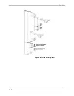
Page 13: ...Introduction N 595 5 Figure 4 Trend Softkey Map...
Page 50: ...This page intentionally left blank...
Page 76: ...This page intentionally left blank...
Page 82: ...This page intentionally left blank...
Page 96: ...This page intentionally left blank...
Page 98: ...Data Port Interface Protocol 90 Figure 19 Data Port Setup...
Page 116: ...This page intentionally left blank...
Page 125: ...Figure 27 Main PCB Schematic Diagram Sheet 1 of 13 117...
Page 126: ...Figure 28 Main PCB Schematic Diagram Sheet 2 of 13 119...
Page 127: ...Figure 29 Main PCB Schematic Diagram Sheet 3 of 13 121...
Page 128: ...Figure 30 Main PCB Schematic Diagram Sheet 4 of 13 123...
Page 129: ...Figure 31 Main PCB Schematic Diagram Sheet 5 of 13 125...
Page 130: ...Figure 32 Main PCB Schematic Diagram Sheet 6 of 13 127...
Page 131: ...Figure 33 Main PCB Schematic Diagram Sheet 7 of 13 129...
Page 132: ...Figure 34 Main PCB Schematic Diagram Sheet 8 of 13 131...
Page 133: ...Figure 35 Main PCB Schematic Diagram Sheet 9 of 13 133...
Page 134: ...Figure 36 Main PCB Schematic Diagram Sheet 10 of 13 135...
Page 135: ...Figure 37 Main PCB Schematic Diagram Sheet 11 of 13 137...
Page 136: ...Figure 38 Main PCB Schematic Diagram Sheet 12 of 13 139...
Page 137: ...Figure 39 Main PCB Schematic Diagram Sheet 13 of 13 141...
Page 138: ...Figure 40 Main PCB Assembly Drawing Front View 143...
Page 141: ...Figure 43 Linear Power Supply Assembly Drawing 149 AC FERRITE DC FERRITE...

