Power-On Settings and Service Functions
N-595
31
Service
Functions
Service functions can be used to select institutional defaults and to access
information about the patient or instrument. Only a Nellcor Customer Service
Engineer should access some of the items available through the service
functions. These items will be noted in the text that follows.
Accessing the
Service Functions
All service functions are accessible only if the DOC-10 pulse oximetry cables
are disconnected from the monitor.
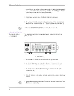
1. Turn on the N-595 by pressing the POWER ON/OFF button.
2. Wait for monitor power-on self-test to complete.
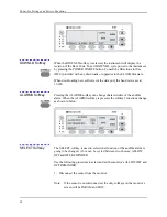
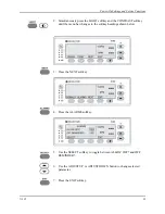
3. Simultaneously press and hold the LIGHT softkey and the CONTRAST
button until the service softkeys are displayed.
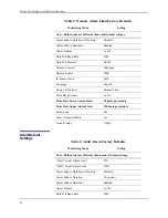
Data Port Protocol
ASCII
Display Contrast
Midrange
Display Format
Pleth
In-Sensor Trend
SpO
2
Language
English
Nurse Call Polarity
Normally Low
Pulse Beep Volume
4 of 10
Pulse Rate Lower Alarm Limit
40 beats per minute
Pulse Rate Upper Alarm Limit
170 beats per minute
SatSeconds
Off
Sensor Adjust Enabled
Yes
Trend Display
%SpO
2
Table 3: Adult Alarm Factory Defaults
Monitoring Mode
Setting
Note: Bold entries are different than neonate default settings.
Summary of Contents for OXIMAX N-595
Page 1: ......
Page 8: ...This page intentionally left blank...
Page 13: ...Introduction N 595 5 Figure 4 Trend Softkey Map...
Page 50: ...This page intentionally left blank...
Page 76: ...This page intentionally left blank...
Page 82: ...This page intentionally left blank...
Page 96: ...This page intentionally left blank...
Page 98: ...Data Port Interface Protocol 90 Figure 19 Data Port Setup...
Page 116: ...This page intentionally left blank...
Page 125: ...Figure 27 Main PCB Schematic Diagram Sheet 1 of 13 117...
Page 126: ...Figure 28 Main PCB Schematic Diagram Sheet 2 of 13 119...
Page 127: ...Figure 29 Main PCB Schematic Diagram Sheet 3 of 13 121...
Page 128: ...Figure 30 Main PCB Schematic Diagram Sheet 4 of 13 123...
Page 129: ...Figure 31 Main PCB Schematic Diagram Sheet 5 of 13 125...
Page 130: ...Figure 32 Main PCB Schematic Diagram Sheet 6 of 13 127...
Page 131: ...Figure 33 Main PCB Schematic Diagram Sheet 7 of 13 129...
Page 132: ...Figure 34 Main PCB Schematic Diagram Sheet 8 of 13 131...
Page 133: ...Figure 35 Main PCB Schematic Diagram Sheet 9 of 13 133...
Page 134: ...Figure 36 Main PCB Schematic Diagram Sheet 10 of 13 135...
Page 135: ...Figure 37 Main PCB Schematic Diagram Sheet 11 of 13 137...
Page 136: ...Figure 38 Main PCB Schematic Diagram Sheet 12 of 13 139...
Page 137: ...Figure 39 Main PCB Schematic Diagram Sheet 13 of 13 141...
Page 138: ...Figure 40 Main PCB Assembly Drawing Front View 143...
Page 141: ...Figure 43 Linear Power Supply Assembly Drawing 149 AC FERRITE DC FERRITE...


