N-595
69
S p a r e P a r t s
Introduction
The latest version of this manual is available on the Internet at:
http://www.mallinckrodt.com/respiratory/resp/Serv_Supp/ProductManuals.html
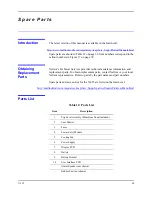
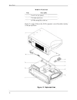
Spare parts are shown in Table 12 on page 69. Item numbers correspond to the
callout numbers in Figure 17 on page 70.
Obtaining
Replacement
Parts
Nellcor's Technical Services provides technical assistance information and
replacement parts. To obtain replacement parts, contact Nellcor or your local
Nellcor representative. Refer to parts by the part names and part numbers.
Spare parts and accessories for the N-595 are listed on the Internet at:
http://mallinckrodt.com/respiratory/resp/Serv_Supp/Apartweb/main/PartAcceMenu.html
Parts List
Table 12: Parts List
Item
Description
1
Top Case Assembly (Membrane Panel included)
2
Fuse Drawer
3
Fuses
4
Power Entry Module
5
Cooling Fan
6
Power Supply
7
Display PCB
8
Battery
9
Battery Bracket
10
User Interface PCB
...
Alarm Speaker (not shown)
...
Rubber Feet (not shown)
Summary of Contents for OXIMAX N-595
Page 1: ......
Page 8: ...This page intentionally left blank...
Page 13: ...Introduction N 595 5 Figure 4 Trend Softkey Map...
Page 50: ...This page intentionally left blank...
Page 76: ...This page intentionally left blank...
Page 82: ...This page intentionally left blank...
Page 96: ...This page intentionally left blank...
Page 98: ...Data Port Interface Protocol 90 Figure 19 Data Port Setup...
Page 116: ...This page intentionally left blank...
Page 125: ...Figure 27 Main PCB Schematic Diagram Sheet 1 of 13 117...
Page 126: ...Figure 28 Main PCB Schematic Diagram Sheet 2 of 13 119...
Page 127: ...Figure 29 Main PCB Schematic Diagram Sheet 3 of 13 121...
Page 128: ...Figure 30 Main PCB Schematic Diagram Sheet 4 of 13 123...
Page 129: ...Figure 31 Main PCB Schematic Diagram Sheet 5 of 13 125...
Page 130: ...Figure 32 Main PCB Schematic Diagram Sheet 6 of 13 127...
Page 131: ...Figure 33 Main PCB Schematic Diagram Sheet 7 of 13 129...
Page 132: ...Figure 34 Main PCB Schematic Diagram Sheet 8 of 13 131...
Page 133: ...Figure 35 Main PCB Schematic Diagram Sheet 9 of 13 133...
Page 134: ...Figure 36 Main PCB Schematic Diagram Sheet 10 of 13 135...
Page 135: ...Figure 37 Main PCB Schematic Diagram Sheet 11 of 13 137...
Page 136: ...Figure 38 Main PCB Schematic Diagram Sheet 12 of 13 139...
Page 137: ...Figure 39 Main PCB Schematic Diagram Sheet 13 of 13 141...
Page 138: ...Figure 40 Main PCB Assembly Drawing Front View 143...
Page 141: ...Figure 43 Linear Power Supply Assembly Drawing 149 AC FERRITE DC FERRITE...

