Modifying and Testing the Oximeter
116
10030881 Rev. B 12-2008
Service Manual
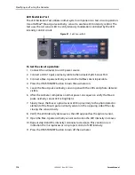
LED Excitation Test
The LED Excitation Test utilizes normal system components to test circuit operation.
Use a OxiMax™ Max-A pulse oximetry sensor to examine LED intensity control. The
test uses the red sensor LED to verify intensity modulation controlled by the LED
intensity control circuit.
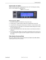
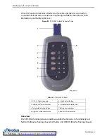
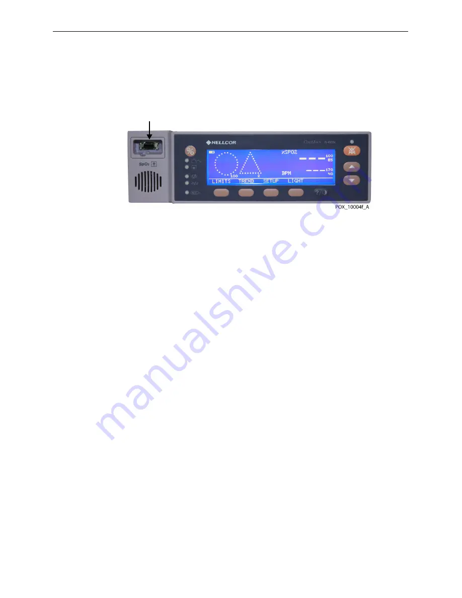
Figure 81.
SpO
2
Sensor Port
To test the circuit operation:
1. Connect the oximeter to an AC power source.
2. Connect a DOC-10 pulse oximetry cable to the oximeter SpO
2
Sensor Port.
3. Connect a Max-A pulse oximetry sensor to the OxiMax sensor input cable.
4. Press the ON/STANDBY button to turn the oximeter on.
5. Leave the Max-A pulse oximetry sensor open with the LEDs and photo detector
visible.
6. After the oximeter completes a normal power-on sequence, verify the Max-A
pulse oximetry sensor LED is brightly lit.
7. Slowly move the Max-A optical sensor LED in proximity to the photo detector
element of the Max-A pulse oximetry sensor on the opposing side of the clip,
closing the sensor slowly.
8. Verify the LED intensity decreases as the LED approaches the optical sensor.
9. Open the Max-A pulse oximetry sensor and notice the LED intensity increases.
10. Repeat step 8 and the intensity continues to decrease. This variation is an
indication the microprocessor is in proper control of LED intensity.
11. Press the ON/STANDBY button to turn off the oximeter.
Summary of Contents for OXIMAX N-600X Series
Page 8: ...viii 10030881 Rev B 12 2008 Service Manual...
Page 12: ...Safety Information 12 10030881 Rev B 12 2008 Service Manual...
Page 44: ...Theory of Operations 44 10030881 Rev B 12 2008 Service Manual...
Page 96: ...Managing the Data Port 96 10030881 Rev B 12 2008 Service Manual...
Page 188: ...Oximeter Schematics 188 10030881 Rev B 12 2008 Service Manual Main PCB Schematic Sheet 1 of 13...
Page 189: ...Service Manual 10030881 Rev B 12 2008 189 Main PCB Schematic Sheet 2 of 13...
Page 191: ...Service Manual 10030881 Rev B 12 2008 191 Main PCB Schematic Sheet 4 of 13...
Page 192: ...Oximeter Schematics 192 10030881 Rev B 12 2008 Service Manual Main PCB Schematic Sheet 5 of 13...
Page 194: ...Oximeter Schematics 194 10030881 Rev B 12 2008 Service Manual Main PCB Schematic Sheet 7 of 13...
Page 195: ...Service Manual 10030881 Rev B 12 2008 195 Main PCB Schematic Sheet 8 of 13...
Page 197: ...Service Manual 10030881 Rev B 12 2008 197 Main PCB Schematic Sheet 10 of 13...
Page 200: ...Service Manual 10030881 Rev B 12 2008 200 Main PCB Schematic Sheet 13 of 13...
Page 201: ...Service Manual 10030881 Rev B 12 2008 201 Main PCB Assembly Drawing Front View...
Page 204: ...Oximeter Schematics 204 10030881 Rev B 12 2008 Service Manual...
Page 209: ......

