Performance Tests
Service Manual
10030881 Rev. B 12-2008
117
Operation with a Live Subject
Patient monitoring involves connecting the Durasensor™ DS-100A pulse oximetry
sensor to a live subject for a qualitative test.
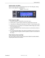
Figure 82.
SpO
2
Sensor Port
To test using a live subject:
1. Ensure the oximeter is connected to an AC power source.
2. Connect a DOC-10 pulse oximetry cable to the oximeter SpO
2
Sensor Port.
3. Connect the DS-100A pulse oximetry sensor to the DOC-10 pulse oximetry cable.
4. Attach the sensor to a live subject as recommended in the OxiMax pulse oximetry
sensor's
Directions For Use
.
5. Press the ON/STANDBY button to turn the oximeter on and verify the oximeter is
operating.
6. The oximeter should stabilize on the subject's physiological signal in about 15 to
30 seconds. Verify the oxygen saturation and pulse rate values are reasonable for
the subject.
Pulse Oximetry Functional Tests
These tests utilize the pulse oximetry functional tester (Nellcor model SRC-MAX) to
verify the performance of the oximeter.
Summary of Contents for OXIMAX N-600X Series
Page 8: ...viii 10030881 Rev B 12 2008 Service Manual...
Page 12: ...Safety Information 12 10030881 Rev B 12 2008 Service Manual...
Page 44: ...Theory of Operations 44 10030881 Rev B 12 2008 Service Manual...
Page 96: ...Managing the Data Port 96 10030881 Rev B 12 2008 Service Manual...
Page 188: ...Oximeter Schematics 188 10030881 Rev B 12 2008 Service Manual Main PCB Schematic Sheet 1 of 13...
Page 189: ...Service Manual 10030881 Rev B 12 2008 189 Main PCB Schematic Sheet 2 of 13...
Page 191: ...Service Manual 10030881 Rev B 12 2008 191 Main PCB Schematic Sheet 4 of 13...
Page 192: ...Oximeter Schematics 192 10030881 Rev B 12 2008 Service Manual Main PCB Schematic Sheet 5 of 13...
Page 194: ...Oximeter Schematics 194 10030881 Rev B 12 2008 Service Manual Main PCB Schematic Sheet 7 of 13...
Page 195: ...Service Manual 10030881 Rev B 12 2008 195 Main PCB Schematic Sheet 8 of 13...
Page 197: ...Service Manual 10030881 Rev B 12 2008 197 Main PCB Schematic Sheet 10 of 13...
Page 200: ...Service Manual 10030881 Rev B 12 2008 200 Main PCB Schematic Sheet 13 of 13...
Page 201: ...Service Manual 10030881 Rev B 12 2008 201 Main PCB Assembly Drawing Front View...
Page 204: ...Oximeter Schematics 204 10030881 Rev B 12 2008 Service Manual...
Page 209: ......


