General Introduction
18
10030881 Rev. B 12-2008
Service Manual
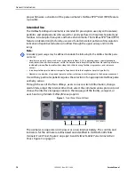
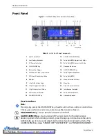
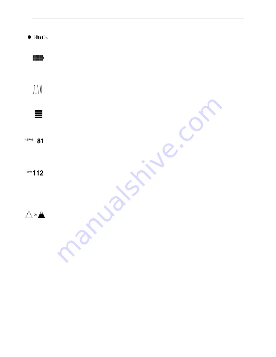
Data In-Sensor Indicator
—Lights to indicate that the attached OxiMax pulse
oximetry sensor contains a patient sensor event record. The sensor event record
information may be viewed or printed.
Battery Fuel Gauge
—Displays the battery charge remaining on the oximeter. The
battery fuel gauge consists of four bars, each corresponding to approximately 1.5
hours of operating time. All four bars are lit when the battery is fully charged. No bars
are lit when a low battery condition exists. Visible in all display views. See
Plethysmographic (pleth) Waveform
—This non-normalized waveform uses real-
time sensor signals, reflecting relative pulsatile strength and quality of incoming
signals. This indicator is only available in the pleth display view.
Pulse Amplitude (blip bar)
—Indicates pulse beat and the relative (non-normalized)
pulse amplitude. As the detected pulse becomes stronger, more bars light with each
pulse. This indicator is only available in the blip and general care format (GCF) display
views.
%SpO2
Value
—Indicates hemoglobin oxygen saturation levels. The display value
flashes zeros during loss-of-pulse alarms and flashes the %SpO
2
value when the
SpO
2
is outside the alarm limits. The oximeter continues to update the display during
Pulse Search. Current upper and lower alarm limit settings appear as smaller values
to the right of the dynamic %SpO
2
value. Visible in all display views.
Pulse Rate Value
—Displays the pulse rate in beats per minute. It flashes during
loss-of-pulse alarms and when the pulse rate is outside of the alarm limits. During
Pulse Search, the oximeter continues to update the display. Pulse rates outside of the
pulse rate range of 20 to 250 bpm are displayed as 0 and 250, respectively. Current
upper and lower alarm limit settings appear as smaller values to the right of the
dynamic pulse rate value. Visible in all display views.
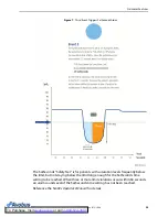
Saturation Pattern Detection (SPD) Icon—
The OxiMax SPD™ Alert (SPD) feature
detects patterns of desaturation in the SpO
2
trend in adults. When the SPD feature is
enabled, the oximeter detects patterns of desaturation indicative of repetitive
reductions in airflow through a patient’s upper airway into the lungs. When the SPD
feature detects patterns of desaturation in the SpO
2
trend in adults, caregivers are
alerted to these patterns via a visual indicator, and optionally, an audio alarm. The
triangle icon for OxiMax SPD™ Alert appears on the monitor display when the feature
is enabled. The triangle fills from the bottom to the top as patterns become more
severe. The triangle empties from top to bottom as the patterns become less severe.
If the triangle fills, an alarm sounds. With Saturation Pattern Detection enabled, the
default setting is On with the sensitivity set to 1. The feature can be turned off in the
LIMITS menu. Caregivers can select from three alarm sensitivity settings: 1 (most
sensitive), 2 (medium sensitivity) or 3 (least sensitive), with 1 resulting in more alarms
and 3 resulting in fewer alarms. The rate at which the SPD icon fills depends on the
SPD sensitivity setting. To explore activation, contact Nellcor’s Technical Services
Department at 1.800.635.5267 or your local Nellcor representative. To use the
feature, reference the
N-600x Operator’s Manual
.
Summary of Contents for OXIMAX N-600X Series
Page 8: ...viii 10030881 Rev B 12 2008 Service Manual...
Page 12: ...Safety Information 12 10030881 Rev B 12 2008 Service Manual...
Page 44: ...Theory of Operations 44 10030881 Rev B 12 2008 Service Manual...
Page 96: ...Managing the Data Port 96 10030881 Rev B 12 2008 Service Manual...
Page 188: ...Oximeter Schematics 188 10030881 Rev B 12 2008 Service Manual Main PCB Schematic Sheet 1 of 13...
Page 189: ...Service Manual 10030881 Rev B 12 2008 189 Main PCB Schematic Sheet 2 of 13...
Page 191: ...Service Manual 10030881 Rev B 12 2008 191 Main PCB Schematic Sheet 4 of 13...
Page 192: ...Oximeter Schematics 192 10030881 Rev B 12 2008 Service Manual Main PCB Schematic Sheet 5 of 13...
Page 194: ...Oximeter Schematics 194 10030881 Rev B 12 2008 Service Manual Main PCB Schematic Sheet 7 of 13...
Page 195: ...Service Manual 10030881 Rev B 12 2008 195 Main PCB Schematic Sheet 8 of 13...
Page 197: ...Service Manual 10030881 Rev B 12 2008 197 Main PCB Schematic Sheet 10 of 13...
Page 200: ...Service Manual 10030881 Rev B 12 2008 200 Main PCB Schematic Sheet 13 of 13...
Page 201: ...Service Manual 10030881 Rev B 12 2008 201 Main PCB Assembly Drawing Front View...
Page 204: ...Oximeter Schematics 204 10030881 Rev B 12 2008 Service Manual...
Page 209: ......

