Operating the Oximeter
58
10030881 Rev. B 12-2008
Service Manual
Note:
For standard usage, connect sensor cables prior to turning on the oximeter. Do NOT connect
any sensor cables to the oximeter when verifying oximeter functionality as part of
performance testing.
1. Connect the oximeter to an AC power source. The oximeter can run on battery
power, but for performance testing, use an AC power source.
2. Verify the oximeter is off and the AC Power Indicator is lit.
3. Turn on the oximeter by pressing the ON/STANDBY key.
4. Ensure all of the front panel indicators illuminate for about two seconds.
a. Within ten seconds, all LEDs, pixels and the backlight should illuminate.
b. The indicators should remain lit for two seconds.
c. The LCD display should show the NELLCOR logo and the firmware version of the
OxiMax N-600x pulse oximeter.
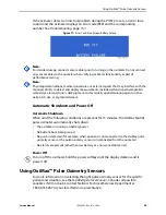
5. Observe the LCD screen for the POST splash screen, which displays for
approximately five seconds.
6. Listen for three ascending tones, then a one-second beep, indicating proper
operation of the speaker and successful completion of the power-on self-tests.
Figure 18.
POST Splash Screen
Note:
The firmware version shown above is only a sample. Check the oximeter for the currently
installed firmware version and record it prior to contacting technical assistance. Always have
it available when contacting Nellcor’s Technical Services Department or a local Nellcor
representative for technical assistance.
7. Ensure all indicators turn off except the AC Power/Battery Charging indicator and
the LCD screen.
The oximeter begins normal operation.
To Purchase, Visit
Summary of Contents for OXIMAX N-600X Series
Page 8: ...viii 10030881 Rev B 12 2008 Service Manual...
Page 12: ...Safety Information 12 10030881 Rev B 12 2008 Service Manual...
Page 44: ...Theory of Operations 44 10030881 Rev B 12 2008 Service Manual...
Page 96: ...Managing the Data Port 96 10030881 Rev B 12 2008 Service Manual...
Page 188: ...Oximeter Schematics 188 10030881 Rev B 12 2008 Service Manual Main PCB Schematic Sheet 1 of 13...
Page 189: ...Service Manual 10030881 Rev B 12 2008 189 Main PCB Schematic Sheet 2 of 13...
Page 191: ...Service Manual 10030881 Rev B 12 2008 191 Main PCB Schematic Sheet 4 of 13...
Page 192: ...Oximeter Schematics 192 10030881 Rev B 12 2008 Service Manual Main PCB Schematic Sheet 5 of 13...
Page 194: ...Oximeter Schematics 194 10030881 Rev B 12 2008 Service Manual Main PCB Schematic Sheet 7 of 13...
Page 195: ...Service Manual 10030881 Rev B 12 2008 195 Main PCB Schematic Sheet 8 of 13...
Page 197: ...Service Manual 10030881 Rev B 12 2008 197 Main PCB Schematic Sheet 10 of 13...
Page 200: ...Service Manual 10030881 Rev B 12 2008 200 Main PCB Schematic Sheet 13 of 13...
Page 201: ...Service Manual 10030881 Rev B 12 2008 201 Main PCB Assembly Drawing Front View...
Page 204: ...Oximeter Schematics 204 10030881 Rev B 12 2008 Service Manual...
Page 209: ......


