Managing the Data Port
82
10030881 Rev. B 12-2008
Service Manual
3.
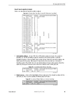
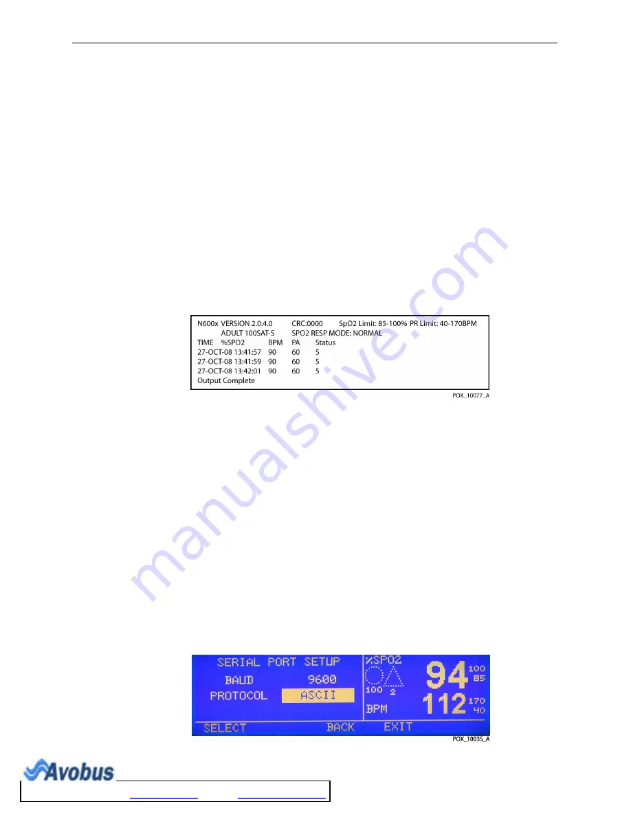
Dump Trend
—Obtain current trend information. View up to 45 hours of trend
information. Information presented includes:
•
Printout Type
•
Oximeter Type
•
Software Revision and CRC data
•
%SpO
2
and Pulse Rate Limit Settings
•
Adult or Neonate Setting
•
Response Mode
•
Date And Time
•
%SpO
2
•
Pulse Rate
•
Pulse Amplitude
•
Status
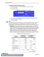
Figure 39.
Sample Trend Dump
4.
Dump Error Log
—Intended for Nellcor’s personnel to obtain or view information
from memory that includes instrument type, software revision level, printout
type, time of printout, operating time of the recorded error, error number, task
number, address, and count.
5.
Exit Interactive Mode
—Closes the interactive mode and returns the data port to
normal operation.
To establish data port communication
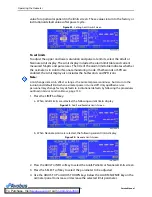
1. Use the Data Port Setup display to set the baud rate and the protocol of the data
port on the OxiMax N-600x pulse oximeter.
2. With the oximeter in the normal monitoring mode, press the SETUP softkey.
3. Press the NEXT softkey twice and then press the COMM softkey.
4. Press the SELECT softkey.
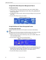
Figure 40.
Serial Port Setup Screen, Baud RateProtocol Selection
To Purchase, Visit
Summary of Contents for OXIMAX N-600X Series
Page 8: ...viii 10030881 Rev B 12 2008 Service Manual...
Page 12: ...Safety Information 12 10030881 Rev B 12 2008 Service Manual...
Page 44: ...Theory of Operations 44 10030881 Rev B 12 2008 Service Manual...
Page 96: ...Managing the Data Port 96 10030881 Rev B 12 2008 Service Manual...
Page 188: ...Oximeter Schematics 188 10030881 Rev B 12 2008 Service Manual Main PCB Schematic Sheet 1 of 13...
Page 189: ...Service Manual 10030881 Rev B 12 2008 189 Main PCB Schematic Sheet 2 of 13...
Page 191: ...Service Manual 10030881 Rev B 12 2008 191 Main PCB Schematic Sheet 4 of 13...
Page 192: ...Oximeter Schematics 192 10030881 Rev B 12 2008 Service Manual Main PCB Schematic Sheet 5 of 13...
Page 194: ...Oximeter Schematics 194 10030881 Rev B 12 2008 Service Manual Main PCB Schematic Sheet 7 of 13...
Page 195: ...Service Manual 10030881 Rev B 12 2008 195 Main PCB Schematic Sheet 8 of 13...
Page 197: ...Service Manual 10030881 Rev B 12 2008 197 Main PCB Schematic Sheet 10 of 13...
Page 200: ...Service Manual 10030881 Rev B 12 2008 200 Main PCB Schematic Sheet 13 of 13...
Page 201: ...Service Manual 10030881 Rev B 12 2008 201 Main PCB Assembly Drawing Front View...
Page 204: ...Oximeter Schematics 204 10030881 Rev B 12 2008 Service Manual...
Page 209: ......


