Managing the Data Port
Service Manual
10030881 Rev. B 12-2008
91
8.
Patient data
—
Presented in the chart from left to right.
- Time the patient data was recorded
- Current SpO
2
value
- Current Pulse Rate (BPM)
- Current Pulse Amplitude (PA)
- Operating status of the oximeter
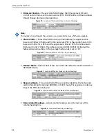
a.
Time
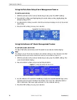
—The Time column displays the value of the real-time clock.
Figure 54.
Location of Time Stamp
b.
Patient Data
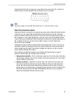
—Parameter values are displayed directly beneath the heading for each
parameter. In this example, the %SpO
2
is 100 and the pulse rate is 190 beats per
minute. The “*” next to the 190 indicates that 190 beats per minute is outside of the
alarm limits, indicated in the top row, for pulse rate. If no data for a parameter is
available, three dashes [- - -] display. PA represents the pulse amplitude value, in which
the number can range from 0 to 254. There are no alarm parameters for this value. It
can be used for trending information as an indication of a change in pulse volume,
relative pulse strength, or circulation.
Figure 55.
Location of Patient Data
Note:
A sensor disconnect causes three dashes [- - -] to be displayed in the patient data section of
the display or printout.
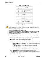
c.
Operating Status
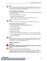
—The Status column indicates alarm conditions and operating
status of the oximeter. In this example, “PH” (Pulse High) indicates the pulse rate
upper alarm limit has been exceeded. A complete listing of the status codes is listed
below. As many as four codes can be displayed at one time in the Status column.
Figure 56.
Location of Operating Status Data
Table 17.
Status Code Definitions
Code
Definition
AO
Alarm Off
AS
Alarm Silence
BU
Battery in Use
To Purchase, Visit
Summary of Contents for OXIMAX N-600X Series
Page 8: ...viii 10030881 Rev B 12 2008 Service Manual...
Page 12: ...Safety Information 12 10030881 Rev B 12 2008 Service Manual...
Page 44: ...Theory of Operations 44 10030881 Rev B 12 2008 Service Manual...
Page 96: ...Managing the Data Port 96 10030881 Rev B 12 2008 Service Manual...
Page 188: ...Oximeter Schematics 188 10030881 Rev B 12 2008 Service Manual Main PCB Schematic Sheet 1 of 13...
Page 189: ...Service Manual 10030881 Rev B 12 2008 189 Main PCB Schematic Sheet 2 of 13...
Page 191: ...Service Manual 10030881 Rev B 12 2008 191 Main PCB Schematic Sheet 4 of 13...
Page 192: ...Oximeter Schematics 192 10030881 Rev B 12 2008 Service Manual Main PCB Schematic Sheet 5 of 13...
Page 194: ...Oximeter Schematics 194 10030881 Rev B 12 2008 Service Manual Main PCB Schematic Sheet 7 of 13...
Page 195: ...Service Manual 10030881 Rev B 12 2008 195 Main PCB Schematic Sheet 8 of 13...
Page 197: ...Service Manual 10030881 Rev B 12 2008 197 Main PCB Schematic Sheet 10 of 13...
Page 200: ...Service Manual 10030881 Rev B 12 2008 200 Main PCB Schematic Sheet 13 of 13...
Page 201: ...Service Manual 10030881 Rev B 12 2008 201 Main PCB Assembly Drawing Front View...
Page 204: ...Oximeter Schematics 204 10030881 Rev B 12 2008 Service Manual...
Page 209: ......


