background image

Technical Discussion

90

This Page Intentionally Blank

Summary of Contents for Oximax NPB-40

Page 1: ......

Page 2: ...Nellcor s Technical Services Department or your local representative Purchase of this instrument confers no express or implied license under any Nellcor Puritan Bennett patent to use the instrument wi...

Page 3: ...Installation 12 Performance Verification 15 Introduction 15 Equipment Needed 15 Performance Tests 15 Power On Self Test 15 Discussion 15 Procedure 16 Operational Setup 19 Setting the Time and Date 20...

Page 4: ...59 Returning the NPB 40 59 Repacking in Original Carton 59 Packing in a Different Carton 60 Specifications 63 Performance 63 Electrical 67 Environmental Conditions 68 Physical Characteristics 69 Compl...

Page 5: ...Contents NPB 40 iii Power Supply 81 Power Supply Monitoring 81 Index 103...

Page 6: ...re 18 Display PCB and CPU PCB Removal 52 Figure 19 Battery Spring Alignment 53 Figure 20 Installing The Case Screws 53 Figure 21 Battery Installation 54 Figure 22 Battery Compartment Door Latch 54 Fig...

Page 7: ...b l e s Table 1 Menu Structure 7 Table 2 Time Set Menu 8 Table 3 Troubleshooting Guide 34 Table 4 Error Codes 37 Table 5 Parts and Accessories List 55 Table 6 Electronic Emissions 71 Table 7 Electrom...

Page 8: ...Tables vi This Page Intentionally Blank...

Page 9: ...ovided by the NPB 40 WARNING Explosion hazard Do not use the NPB 40 in the presence of flammable anesthetics mixed with air oxygen or nitrous oxide WARNING Do not spray pour or spill any liquid on the...

Page 10: ...case rendering it unusable Caution When installing the Power Supply or the User Interface PCB tighten the seven screws to a maximum of four inch pounds Over tightening could strip out the screw holes...

Page 11: ...rate of adult pediatric and neonatal patients It can be used in hospital emergency transport and mobile environments as well as in the home care environment Identification of Front Panel Buttons and...

Page 12: ...icator blip bar 8 Time colon time date field separator 9 Adjust Time mode indicator 10 Adjust Volume mode indicator 11 Set Limit mode indicator 12 BPM Upper Alarm Limit indicator 13 BPM Limit Changed...

Page 13: ...ndicator 18 Print indicator 19 Motion indicator 20 Pulse Beep Tone Volume Adjust indicator 21 Pulse Search indicator 22 Alarm Volume Adjust indicator 23 Data In Sensor indicator 24 Data indicator 25 L...

Page 14: ...larm volume pulse beep volume and data printing Pressing the Menu button during start up Power On Self Test POST test accesses the Time Date setting menu Repeated activations of the Menu button in thi...

Page 15: ...Low Limit Adjust limit 2 SpO2 High Limit Adjust limit 3 BPM Low Limit Adjust limit 4 BPM High Limit Adjust limit 5 Pulse Beep Volume Adjust volume Indications on blip bar 6 Alarm Volume Adjust volume...

Page 16: ...ecks the day and month selections to see if they are correct If the day or month selection is not valid for the year selected the NPB 40 display returns to the day selection display Some examples of i...

Page 17: ...efer to the NPB 40 operator s manual To understand the various Nellcor approved OXIMAX sensors that work with the NPB 40 refer to the individual OXIMAX sensor s Directions For Use The latest version o...

Page 18: ...Introduction 10 This Page Intentionally Blank...

Page 19: ...model has cleaning instructions specific to that sensor Periodic Safety Checks The NPB 40 requires no calibration The following checks should be performed at least every 24 months by a qualified servi...

Page 20: ...d remove the battery access door See Figure 1 3 Install four AA size batteries orientated as shown in Figure 1 4 Replace the battery access door Figure 1 Installing Batteries WARNING Explosion hazard...

Page 21: ...all medical equipment carefully route patient cabling to reduce the possibility of patient entanglement or strangulation WARNING To ensure accurate performance and prevent device failure do not expos...

Page 22: ...Routine Maintenance 14 This Page Intentionally Blank...

Page 23: ...Proper working conditions are verified each time the NPB 40 is turned on as described in the following procedure The verification procedure POST takes 7 to 13 seconds to complete Caution If any indic...

Page 24: ...play graphics are shown for three seconds Display goes blank all display elements off for one second Version number of the software is shown as a three digit number in the right hand number field with...

Page 25: ...s shown with leading zeros for software version numbers less than 100 Note The software version shown above is only a sample Check your NPB 40 for the software version installed Note Software version...

Page 26: ...second tone indicating that the NPB 40 has passed the test WARNING If you do not hear the POST pass tone do not use the NPB 40 WARNING Ensure that the speaker is clear of any obstructions and that th...

Page 27: ...s the Backlight button The backlight turns on 11 Press the Backlight button The backlight turns off Operational Setup The operational setup procedure sets the time and date into the NPB 40 Refer to th...

Page 28: ...0 Note Allowing the NPB 40 to time out 30 seconds sets the currently shown parameter and the NPB 40 display returns to the normal operating display Procedure With the NPB 40 in the normal monitoring m...

Page 29: ...The minutes indication 45 flashes 6 Press the Up Arrow button or the Down Arrow button until the desired minutes are shown 7 Press the Menu button to set the minutes and show the day set display The d...

Page 30: ...he Up Arrow button or the Down Arrow button until the desired month is shown 11 Press the Menu button to set the month and show the year set display The year indication 2004 flashes 12 Press the Up Ar...

Page 31: ...nect a Nellcor OXIMAX MAX A oxygen OXIMAX sensor to the NPB 40 2 Clip the MAX A to the subject as recommended in the OXIMAX sensor s Directions For Use 3 Press the Power button to turn the NPB 40 on a...

Page 32: ...is a brief description of each test Test Setup This procedure establishes the baseline for all the other tests The Test Setup procedure must be performed before performing any or all of the SRC MAX te...

Page 33: ...X sensor attached to a patient indicating low and high light level passing through the patient at the sensor site The test setup procedure sets up Test 4 for low light level Test Setup Note A DEC 4 ex...

Page 34: ...he SRC MAX PULSE RATE 200 LED lights 2 The NPB 40 bpm increases to 200 and stabilize at 200 bpm The test pass criteria is 197 to 203 bpm inclusive 3 The NPB 40 displays 75 SpO2 displays 200 bpm pass c...

Page 35: ...dicator displays low level modulation Test 2 SpO2 1 Press the SRC MAX SpO2 select button The SRC MAX SpO2 90 LED lights 2 The NPB 40 displays three dashes until the SRC MAX stabilizes at 90 SpO2 The t...

Page 36: ...tion Test 3 Modulation Level 1 Press the SRC MAX MODULATION selection button The SRC MAX MODULATION LED lights 2 The NPB 40 pulse blip bar initially increases in amplitude and then stabilizes 3 The NP...

Page 37: ...ip bar decreases in amplitude 8 The NPB 40 displays 75 SpO2 displays 60 bpm alarms Pulse Amplitude indicator displays low level modulation 9 Perform Test 1 BPM on page 26 The pulse amplitue indicator...

Page 38: ...arms pulse amplitue indicator displays high level modulation 4 Perform Test 1 BPM on page 26 The pulse amplitue indicator should indicate high level modulation 5 Perform Test 2 SpO2 on page 27 The pul...

Page 39: ...Perform Test 2 SpO2 on page 27 The pulse amplitue indicator should indicate low level modulation 11 Disconnect all equipment and turn off the NPB 40 Safety Tests The NPB 40 safety tests meet the stan...

Page 40: ...Performance Verification 32 This Page Intentionally Blank...

Page 41: ...open the NPB 40 housing remove and replace components or make adjustments If your medical facility does not have qualified service personnel contact Nellcor s Technical Services or your local Nellcor...

Page 42: ...teries are installed incorrectly or they are backwards Open the battery compartment and if batteries are not installed correctly remove and reinstall the batteries Refer to the NPB 40 Operator s manua...

Page 43: ...on page 46 CPU PC has failed Replace the CPU PCB with a known good PCB See CPU PCB or Display PCB Replacement on page 46 One or more display segments does not work A display PCB component has failed...

Page 44: ...or Display PCB Replacement on page 46 CPU PC has failed Replace the CPU PCB with a known good PCB See CPU PCB or Display PCB Replacement on page 46 The Backlight LEDs on the Display PCB have failed Re...

Page 45: ...PU PC has failed Replace the CPU PCB with a known good PCB See CPU PCB or Display PCB Replacement on page 46 The printer batteries are at or near a voltage too low to operate the printer Install new b...

Page 46: ...nternal register appears modified from expected value 19 X Check replace sensor extension cable SpO2 front end reports signal out of range 48 X Replace SpO2 board SpO2 front end reports spurious inter...

Page 47: ...back end reports incompatible software version 275 X Check replace sensor extension cable SpO2 back end reports incorrect registration number 276 X Replace with OxiMax sensor extension cable SpO2 back...

Page 48: ...able error with SpO2 communication 531 1 2 1 Replace SpO2 board 2 Replace UI board Unrecoverable error with SpO2 communication 532 1 2 1 Replace SpO2 board 2 Replace UI board Unrecoverable error with...

Page 49: ...e and date Invalid time Cannot snapshot 544 X Replace UI board Invalid register value 999 X Replace UI board Watchdog protection activated Table 4 Error Codes Continued Error Code Scope of Action Acti...

Page 50: ...Troubleshooting 42 This Page Intentionally Blank...

Page 51: ...e driver four inch pounds 10 cm kg Replacement Level Supported The replacement level supported for the NPB 40 is to the printed circuit board PCB and major subassembly level When the problem has been...

Page 52: ...ries Figure 4 Installing Batteries Separating the Front and Back Cases Do the following procedure to separate the NPB 40 front and back cases 1 Do the procedure in paragraph Prior to Disassembly on pa...

Page 53: ...semblies See Figure 6 Figure 6 Cases Separated Caution Failure to unlock connector J3 on the CPU PCB before attempting to remove the front case flex circuit could damage the flex circuit 4 Unlock conn...

Page 54: ...ese slots when you remove the CPU PCB and display PCB and ensure that the battery connectors are inserted back into these slots when you reassemble the NPB 40 3 Pull the CPU PCB and display PCB to the...

Page 55: ...gure 9 Separating the Display PCB and CPU PCB 5 Place the defective PCB to the side 6 Align the new PCB J1 and J2 and the removed good PCB J1 and J2 and gently press them together See Figure 10 Figure...

Page 56: ...ttery springs slip into place See Figure 11 Figure 11 Battery Spring Alignment Note The longer screws install at the top of the case See Figure 12 items 1 and 4 8 Align the front and rear cases See Fi...

Page 57: ...e 24 Front Case Assembly Replacement The front case assembly contains the keypad Perform the following procedure to replace the front case assembly 1 Remove the batteries from the NPB 40 See Prior to...

Page 58: ...bly ribbon cable to the CPU PCB connector J3 See Figure 14 Figure 14 Front Case Ribbon Cable Connection 5 Lock the ribbon cable connector See Figure 15 Figure 15 Locking CPU PCB Connection to J3 1 J3...

Page 59: ...hrough 4 Figure 16 Installing The Case Screws 7 Install the batteries and battery cover as shown in Figure 17 Figure 17 Battery Installation 8 Perform the performance verification tests before placing...

Page 60: ...on The battery connectors spring assemblies at the bottom of the CPU PCB are held in slots in the battery compartment Observe how these connectors are engaged in these slots when you remove the CPU PC...

Page 61: ...that the battery springs slip into place See Figure 19 Figure 19 Battery Spring Alignment Note The longer screws install at the top of the case See Figure 20 items 1 and 4 6 Place the front and rear...

Page 62: ...See Pulse Oximetry Functional Tests on page 24 Battery Compartment Door Replacement Perform the following procedure to replace the battery compartment door 1 Press battery door latch Figure 22 item 1...

Page 63: ...arts by the part names and part numbers Spare parts and accessories for the NPB 40 are listed on the Internet at http mallinckrodt com respiratory resp Serv_Supp Apartweb main PartAcceMenu html Parts...

Page 64: ...erman Operator s manual Greek Operator s manual Hungarian Operator s manual Italian Operator s manual Japanese Operator s manual Norwegian Operator s manual Polish Operator s manual Portuguese Operato...

Page 65: ...Spare Parts NPB 40 57 Figure 23 shows the NPB 40 expanded view with numbers relating to the spare parts list Figure 23 Exploded View...

Page 66: ...Spare Parts 58 This Page Intentionally Blank...

Page 67: ...original shipping carton If the original carton is not available use a suitable carton with appropriate packing material to protect it during shipping Return the NPB 40 by any shipping method that pro...

Page 68: ...return address and RGA number Packing in a Different Carton If the original carton is not available use the following procedure to pack the NPB 40 1 Place the NPB 40 in a plastic bag 2 Locate a corru...

Page 69: ...40 61 4 Place the bagged unit on the layer of packing material and fill the box completely with packing material 5 Seal the carton with packing tape 6 Label the carton with the shipping address retur...

Page 70: ...Packing for Shipment 62 This Page Intentionally Blank...

Page 71: ...ts With Motion 2 normal physiologic range 55 125 bpm 5 digits Low Perfusion 3 20 to 250 bpm 3 digits 1 Saturation accuracy will vary by sensor type Refer to the Sensor Accuracy Grid The Sensor Accurac...

Page 72: ...ter Pitch 30 Hz 1500 Hz On pulse width 20 msec 500 msec Off Interval 20 msec 10 msec Number of pulses in burst 1 Repetition Pause 2 sec N A Priority 2 POST Pass Volume level Fixed at 45 dB A at one me...

Page 73: ...Number of pulses in burst 1 Repetition Pause 2 sec N A Priority 6 Pulse Beep Volume level Adjustable 42 to 52 dB A at one meter Pitch 30 Hz 1500 Hz On pulse width 20 msec 50 msec Off Interval 20 msec...

Page 74: ...Adjustable 42 to 52 dB A at one meter Pitch 30 Hz 752 Hz On pulse width 20 msec 400 msec Off Interval 20 msec 300 msec Number of pulses in burst 1 Repetition Pause 2 sec 0 sec Priority 10 Low priorit...

Page 75: ...light emitted are near 660 nm and 890 nm OXIMAX Sensor Power Dissipation Sensor Dissipation OXIMAX MAX N 52 5 mW OXIMAX MAX I 52 5 mW OXIMAX MAX P 52 5 mW OXIMAX MAX A 52 5 mW OXIMAX MAX AL 52 5 mW O...

Page 76: ...orage not in shipping container Temperature 20 C to 60 C 4 F to 140 F Altitude 390 m to 5 574 m 1 280 ft to 18 288 ft Atmospheric Pressure 50 kPa to 106 kPa 14 7 in Hg to 31 3 in Hg Relative Humidity...

Page 77: ...Standards EN 60601 1 1990 A1 A2 EN 60601 1 2 2001 UL 60601 1 CAN CSA C22 2 No 601 1 Type of protection Internally powered equipment on battery power Degree of protection Type BF Applied part Mode of...

Page 78: ...00 MHz to 2 5 GHz Equation Rated Maximum Output Power of Transmitter in Watts Separation Distance in Meters Separation Distance in Meters Separation Distance in Meters 0 01 0 12 0 12 0 23 0 1 0 38 0 3...

Page 79: ...tic Environment Guidance RF emissions CISPR 11 Group 1 The NPB 40 uses RF energy only for its internal function Therefore the RF emissions are very low and not likely to cause interference in nearby e...

Page 80: ...n power should be that of a typical commercial or hospital environment Power Frequency 50 60 Hz magnetic field 3 A m Complies Power frequency magnetic fields should be at levels characteristic of a ty...

Page 81: ...s amateur radio AM and FM radio broadcast and TV broadcast cannot be predicted theoretically with accuracy To assess the electromagnetic environment due to fixed RF transmitters an electromagnetic sit...

Page 82: ...Specifications 74 This Page Intentionally Blank...

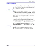
Page 83: ...ared light into an arteriolar bed and measuring changes in light absorption during the pulsatile cycle Red and infrared low voltage light emitting diodes LED in the oximetry OXIMAX sensor serve as lig...

Page 84: ...ables that shift the relationship between PO2 and pH temperature the partial pressure of carbon dioxide PCO2 2 3 DPG and fetal hemoglobin See Figure 25 Figure 25 Oxyhemoglobin Dissociation Curve SatSe...

Page 85: ...rect operation including the OXIMAX sensor s calibration data model type troubleshooting codes and error detection data This unique oximetry architecture enables several new features with the NPB 40 W...

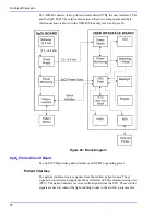
Page 86: ...26 Block Diagram SpO2 Printed Circuit Board The SpO2 PCB provides patient interface and NPB 40 operating power Patient Interface The patient interface receives signals from the OXIMAX patient sensor T...

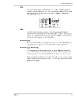
Page 87: ...he SpO2 power supply The SpO2 power monitoring function provides the user interface CPU and SpO2 patient interface with status information on the power supply output signals User Interface Printed Cir...

Page 88: ...CPU controls all functions and timing for the NPB 40 The CPU communicates with the SpO2 PCB patient interface The patient interface signal are sent to the CPU for processing The CPU sends signals to t...

Page 89: ...rinter communicates with the IrDA Refer to the printer manual for more information Power Supply The user interface PCB power supply receives power from the SpO2 PCB power supply The power supply provi...

Page 90: ...Technical Discussion 82 This Page Intentionally Blank...

Page 91: ...9 9K J5 Engineering Mode 1 2 C114 100pF L11 2506033017Y0 1 2 T183 C107 0 1uF T187 C105 0 1uF R98 100K T184 C106 100pF T185 C81 0 1uF T188 J8 1 2 T189 T176 T190 R23 698K C113 0 1uF C109 0 1uF J4 CON8 1...

Page 92: ...Technical Discussion 84 This Page Intentionally Blank...

Page 93: ...C104 4 7U Q10 MPSA06S 3 1 2 T166 R101 301K T167 R102 221K T168 R104 100R T171 R105 100K T169 T175 R96 30 1K R107 49 9K B2 1 T170 R109 PTC1812 Q13 BSS138 1 3 2 Q12 IRLML6401 3 1 2 R93 1K T174 TVS1 SMC...

Page 94: ...Technical Discussion 86 This Page Intentionally Blank...

Page 95: ...U35 LT1790BCS6 1 25 4 6 2 1 VIN VOUT GND GND C74 4 7pf R84 845K C80 1U R87 294K U31 LT1761ES5 5 4 5 1 2 3 BYP OUT IN GND SDN C86 0 1U L9 10uH T137 R89 10R T139 C79 4 7U C77 4 7pf T138 R113 10R C84 0...

Page 96: ...Technical Discussion 88 This Page Intentionally Blank...

Page 97: ...A0 NLB A1 A2 A3 A4 A5 A6 A7 A8 A9 A10 A11 A12 A13 A14 A15 A16 A17 A18 A19 P28 A20 CS7 P29 A21 CS6 P30 A22 CS5 P31 A23 CS4 D0 D1 D2 D3 D4 D5 D6 D7 D8 D9 D10 D11 D12 D13 D14 D15 NCS0 NCS1 P26 NCS2 P27...

Page 98: ...Technical Discussion 90 This Page Intentionally Blank...

Page 99: ...9K T10 T36 U2B MAX4066S 3 5 7 4 14 R20 24 9K C6 0 047U R80 200K C9 22P T15 U3B TLC2262PW 6 5 7 8 4 R17 24 9K C22 0 022U T40 R45 909 R24 71 5K C20 0 047U T16 U25B LT1013S 3 4 5 6 2 T99 R76 49 9K C23 22...

Page 100: ...Technical Discussion 92 This Page Intentionally Blank...

Page 101: ...PSA06S 3 1 2 C10 470P C29 0 01U R75 475 R49 49 9K T60 Q5 MPSA06S 3 1 2 C30 4 7P U14A LT1013S 1 8 7 6 2 C31 0 1U T48 L3 DLW31SN222SQ2B 4 1 3 2 U15 MAX4053Q 11 10 9 6 16 7 8 14 13 12 15 2 1 4 5 3 A B C...

Page 102: ...Technical Discussion 94 This Page Intentionally Blank...

Page 103: ...0 T64 C67 10U 10V T88 RP18 100 1 8 2 7 3 6 4 5 T6 T107 C45 0 1U T73 T69 T67 T2 T117 U18 74LVC244APW 10 1 20 2 4 6 8 19 11 13 15 17 18 16 14 12 9 7 5 3 GND OE1 VCC I0 I1 I2 I3 OE2 I4 I5 I6 I7 O0 O1 O2...

Page 104: ...Technical Discussion 96 This Page Intentionally Blank...

Page 105: ...13 14 R11 1 0M C18 0 1uF C1 0 1uF R48 453K R73 562K C69 0 1uF R12 1 0M R74 649K R3 1 0M T1 R9 1 0M T6 C11 1uF D1 3 6V D2 MBR0520L R8 30 1K C9 0 1uF C3 22mF R10 1 0M T2 T4 R42 1M V GND U7 LP339 1 2 3 4...

Page 106: ...Technical Discussion 98 This Page Intentionally Blank...

Page 107: ...11 A12 A13 A14 A15 A16 A17 A18 A19 P28 A20 CS7 P29 A21 CS6 P30 A22 CS5 P31 A23 CS4 D0 D1 D2 D3 D4 D5 D6 D7 D8 D9 D10 D11 D12 D13 D14 D15 NCS0 NCS1 P26 NCS2 P27 NCS3 NRD NOE NWR0 NWE NWR1 NUB NWAIT P24...

Page 108: ...Technical Discussion 100 This Page Intentionally Blank...

Page 109: ...15 16 17 18 19 20 21 22 23 25 26 27 28 29 30 31 32 33 34 35 36 37 38 39 40 41 42 43 44 45 46 47 48 49 50 51 52 53 54 64 63 58 56 59 57 60 61 62 24 55 SEG1 SEG2 SEG3 SEG4 SEG5 SEG6 SEG7 SEG8 SEG9 SEG10...

Page 110: ...Technical Discussion 102 This Page Intentionally Blank...

Page 111: ...dysfunctional hemoglobin 15 E equipment needed for performance checks 15 Er 18 error codes 37 exploded view 57 explosion hazard 1 extension cable 15 external agents 15 F flammable anesthetics 2 fract...

Page 112: ...safety analyzer 15 safety tests 31 satseconds alarm management 76 sensors 67 separating the front and back cases 44 service manual 9 software version 17 spare parts 55 spare parts on internet 9 speci...

Page 113: ......

Page 114: ...ett Division 4280 Hacienda Drive Pleasanton CA 94588 U S A Telephone 1 800 635 5267 Authorized Representative Tyco Healthcare UK LTD 154 Fareham Road Gosport PO13 0AS U K 2004 Nellcor Puritan Bennett...

Reviews: