background image

Chapter 3  BIOS Setup 

29 

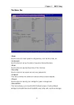
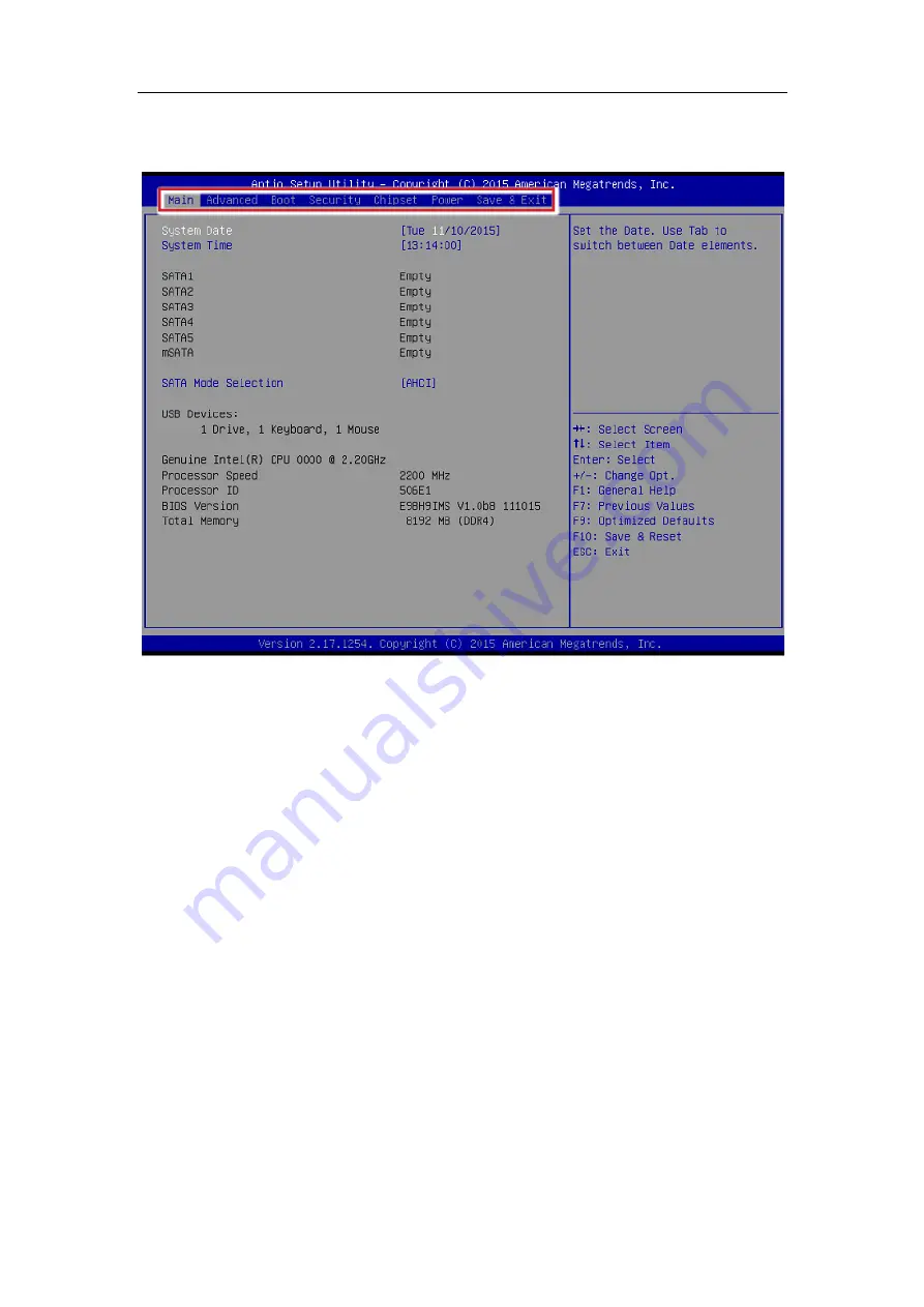
The Menu Bar 


Main


Use


this


menu


for


basic


system


configurations,


such


as


time,


date,


etc.


Advanced


Use


this


menu


to


set


up


the


items


of


special


enhanced


features.


Boot


Use


this


menu


to


specify


the


priority


of


boot


devices.


Security


Use


this


menu


to


set


supervisor


and


user


passwords.


Chipset


This


menu


controls


the


advanced


features


of


the


onboard


chipsets.


Power


Use


this


menu


to


specify


your


settings


for


power


management.


Save


&


Exit


This


menu


allows


you


to


load


the


BIOS


default


values


or


factory


default


settings


into


the


BIOS


and


exit


the


BIOS


setup


utility


with


or


without


changes.


Summary of Contents for AEMC236-990

Page 1: ...AEMC236 990 Intel C236 Express Chipset Industrial Computer Board User s Manual v1 2 Release date 2023 6...

Page 2: ...2 Hardware Setup 12 CPU Central Processing Unit 12 Introduction to LGA 115x CPU 12 CPU Installation 13 Memory 15 Dual Channel Mode 15 Recommended Memory Population 15 Installing Memory Modules 15 Powe...

Page 3: ...per JCOMP1 JCOMP6 25 NVM LAN Jumper JNVM1 25 Slot 25 PCIe Peripheral Component Interconnect Express Slot 25 Mini PCIe Slot 26 PCI Peripheral Component Interconnect Slot 26 Chapter 3 BIOS Setup 27 Ente...

Page 4: ...chnical Support If a problem arises with your system and no solution can be obtained from the user s manual please contact your place of purchase or local distributor Alternatively please try the foll...

Page 5: ...maged Liquid has penetrated into the equipment The equipment has been exposed to moisture The equipment does not work well or you can not get it work according to User s Manual The equipment has dropp...

Page 6: ...lifornia Danger of explosion if battery is incorrectly replaced Replace only with the same or equivalent type recommended by the manufacturer CE Conformity Hereby Micro Star International CO LTD decla...

Page 7: ...IR LA NOTICE D INSTALLATION AVANT DE RACCORDER AU RESEAU This device complies with Part 15 of the FCC Rules Operation is subject to the following two conditions 1 this device may not cause harmful int...

Page 8: ...Preface 7 the EU You can return these products to local collection points...

Page 9: ...station as well as in the future Mainboard Specifications Processor C236 SKU supports 7th 6th Gen Intel Xeon E3 12xx V5 Core i7 i5 i3 Pentium Celeron Processors in socket LGA1151 Chipset C236 SKU Inte...

Page 10: ...h Ring 0V 5V 12V COM3 4 5 6 RS 232 with 0V 5V 12V 6 Serial Port Power select jumpers 2 2 3 pin 2 0 pitch pin headers select Ring 0V 5V 12V for COM1 2 4 1 3 pin 2 0 2 54 pitch pin headers select 0V 5V...

Page 11: ...Storage Temperature 20 80 Humidity 10 90 RH Non Condensing SKU Comparison PCH C236 DIMM slot 4 SATA 6G bs port 5 mSATA slot 1 mini pcie slot 2 Rear panel USB 4 USB 3 0 2 USB 2 0 Onboard USB pin header...

Page 12: ...Chapter 1 Overview 11 Mainboard Layout...

Page 13: ...all the cooler to prevent overheating If you do not have the CPU cooler consult your dealer before turning on the computer Important Overheating Overheating will seriously damage the CPU and system Al...

Page 14: ...en the load lever and remove the plastic cap 2 Lift the load lever up to fully open position 3 After confirming the CPU direction for correct mating put down the CPU in the socket housing frame Be sur...

Page 15: ...ten the cooler Turn over the motherboard to confirm that the clipends are correctly inserted 8 Finally attach the CPU Fan cable to the CPU fan connector on the motherboard Important Confirm if your CP...

Page 16: ...e the same DIMM type in each channel specifically 1 Use the same DIMM size 2 Use the same number of ranks per DIMM Installing Memory Modules 1 The memory module has only one notch on the center and wi...

Page 17: ...system bootup always insert the memory module into the DIMM1 first Power Supply System Power Connector PWRCONN1 This connector allows you to connect a power supply To connect to the power supply make...

Page 18: ...Port The standard PS 2 mouse keyboard DIN connector is for a PS 2 mouse keyboard USB 2 0 Port The USB Universal Serial Bus port is for attaching USB devices such as key board mouse or other USB compat...

Page 19: ...ation D Sub Port The DB15 pin female connector is provided for monitor DisplayPort DisplayPort is a digital display interface standard This connector is used to con nect a monitor with DisplayPort inp...

Page 20: ...o connect System Management Bus SMBus interface GPIO Pin Header JGPIO1 This connector is provided for the General Purpose Input Output GPIO peripheral module Serial ATA Connector SATA1 5 SATA5 for C23...

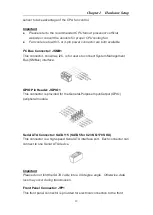
Page 21: ...tivity Design Guide is ideal for connecting high speed USB interface peripherals such as USB HDD digital cameras MP3 players printers modems and the like Important Note that the pins of VCC and GND mu...

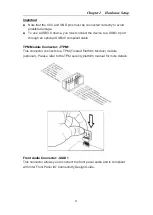
Page 22: ...USB3 0 port through an optional USB3 0 compliant cable TPM Module Connector JTPM1 This connector connects to a TPM Trusted Platform Module module optional Please refer to the TPM security platform man...

Page 23: ...tor JLPT1 The mainboard provides a 26 pin header for connection to an optional parallel port bracket The parallel port is a standard printer port that supports Enhanced Parallel Port EPP and Extended...

Page 24: ...Ready 4 NC No Connection 5 GND Signal Ground 5 GND Signal Ground 6 DSR Data Set Ready 6 NC No Connection 7 RTS Request To Send 7 NC No Connection 8 CTS Clear To Send 8 NC No Connection 9 VCC_CO M1 Vol...

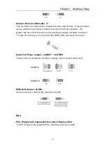
Page 25: ...mage the motherboard Clear CMOS Jumper J_CMOS1 There is a CMOS RAM onboard that has a power supply from an external battery to keep the data of system configuration With the CMOS RAM the system can au...

Page 26: ...is intrusion and a warning message will flash on screen To clear the warning you must enter the BIOS utility and clear the record Serial Port Power Jumper JCOMP1 JCOMP6 These jumpers specify the opera...

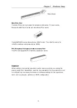
Page 27: ...is for mSATA interface solid state drives SSD PCI Peripheral Component Interconnect Slot The PCI slot supports PCI interface expansion cards Important When adding or removing expansion cards make sure...

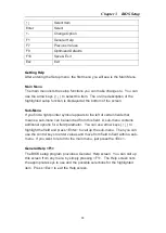
Page 28: ...r should be held for reference only Entering Setup Power on the computer and the system will start POST Power On Self Test process When the message below appears on the screen press DEL or F2 key to e...

Page 29: ...pointer symbol appears to the left of certain fields that means a sub menu can be launched from this field A sub menu contains additional options for a field parameter You can use arrow keys to highli...

Page 30: ...to specify the priority of boot devices Security Use this menu to set supervisor and user passwords Chipset This menu controls the advanced features of the onboard chipsets Power Use this menu to spe...

Page 31: ...setting allows you to set the system date The date format is Day Month Date Year System Time This setting allows you to set the system time The time format is Hour Minute Second SATA Mode Selection Th...

Page 32: ...s BIOS feature often adds 2 3 seconds of delay to the booting sequence This delay ensures that the logo is displayed for a suf ficient amount of time Therefore it is recommended that you disable this...

Page 33: ...ation Serial Port 1 2 3 4 5 6 This setting enables disables the specified serial port Change Settings This setting is used to change the address IRQ settings of the specified serial port Mode Select S...

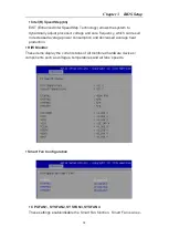
Page 34: ...tion rates and reduces end user response times The technology treats the two cores inside the processor as two logical processors that can execute instructions simultaneously In this way the system pe...

Page 35: ...ich can result in decreased average power consumption and decreased average heat production H W Monitor These items display the current status of all monitored hardware devices components such as volt...

Page 36: ...y USB 1 1 2 0 device in the operating system that does not support or have any USB 1 1 2 0 driver installed such as DOS and SCO Unix Audio Controller This setting enables disables the onboard audio co...

Page 37: ...OS attempts to load the disk operating system Hard Drive BBS Priorities This setting allows users to set the priority of the specified devices First press Enter to enter the sub menu Then you may use...

Page 38: ...up utility User Password User Password controls access to the system at boot and to the BIOS Setup utility Chassis Intrusion The field enables or disables the feature of recording the chassis intrusio...

Page 39: ...tocol and INT1A interface will not be available AMT Configuration Intel Active Management Technology AMT is hardware based technology for remotely managing and securing PCs out of band PCH FW Configur...

Page 40: ...direction Console Redirection operates in host systems that do not have a monitor and keyboard attached This setting enables disables the operation of console redirection When set to Enabled BIOS redi...

Page 41: ...ularly important where the sending device is capable of sending data much faster than the receiving device can receive it VT UTF8 Combo Key Support This setting enables disables the VT UTF8 combinatio...

Page 42: ...system memory made available at boot time by the system BIOS for video Pre allocated memory is also known as locked memory This is because it is locked for video use only and as such is invisible and...

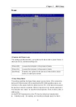
Page 43: ...ure or interrupt occurred Deep Sleep Mode The setting specifies the Deep Sleep power saving mode S5 is almost the same as G3 Mechanical Off except that the PSU still supplies power at a minimum to the...

Page 44: ...t for Windows Sleep S3 and is designed to achieve the above said characteristics We suggest customer don t install iRMT if they need normal S3 Advanced Resume Events Control OnChip GbE USB RING This f...

Page 45: ...ptimized Defaults Use this menu to load the default values set by the motherboard manufacturer specifically for optimal performance of the motherboard Save as User Defaults Save changes as the user s...

Page 46: ...chDog_LDN equ 007h WDT_UNIT equ 60h 60h second 68h minute 40h Disabled Watchdog timer WDT_Timer equ 30 ex 30 seconds Sample code Enable config mode mov dx SIO_INDEX_Port mov al SIO_UnLock_Value out dx...

Page 47: ...v dx SIO_DATA_Port mov al WDT_UNIT out dx al enable reset mov dx SIO_INDEX_Port mov al 0FAh out dx al mov dx SIO_DATA_Port in al dx or al 01h out dx al close config mode mov dx SIO_INDEX_Port mov al S...

Page 48: ...h 22h Bit 4 5 6 7 Sample code 2 2 2 2 SMBUS_BASE_ADDRESS equ F040h IO Address SLAVEADDRESS equ 9Ch Slave Address GPI0_REG equ 42h GPO0_REG equ 22h GPO0_Value equ 00010000b Sample Code 1 Get GPI 0 stat...

Reviews: