background image

DOC-IWS-621/A

MON-920 Flat Screen Monitor User’s Guide

2

MON-920 Flat Screen Monitor
User’s Guide

DOC-IWS-621
Revision A

The MON-920 Industrial Flat Panel User’s Guide (DOC-IWS-621) describes the installation
and operation of these units. This document is based on information available at the time of
its publication. While every effort has been made to be accurate, the information contained
herein does not purport to cover all details or variations in hardware or` software. Nematron
makes no warranty and assumes no responsibility for the completeness, accuracy or
usefulness of the information found in these pages. Nematron further assumes no liability or
responsibility for loss or damage, direct or indirect, arising from the use of this product. No
warranties of documentation or product fitness apply.

Nematron

, PowerVIEW

, NemaSoft

, AutoNet

, and FloPro

 are registered trademarks

of the Nematron Corporation. Industrial Control Computer

, Industrial Workstation

, and

FlexBox

, are trademarks of Nematron Corporation.

All brand and product names are trademarks or registered trademarks of their respective
companies.

Electrical Shock Hazard!

 Do not operate the unit with its back cover removed.

There are hazardous voltages inside. Servicing of the equipment should only be
done by qualified and authorized personnel.

CAUTION! 

Changes or modifications not expressly approved by the manufacturer could void

the user’s authority to operate the equipment.

Note

: The terminal must be mounted in a grounded metal enclosure that provides a clean

and dry environment.

Note

: This equipment has been tested and found to comply with the limits for a Class B

digital device, pursuant to Part 15 of the FCC Rules. These limits are designed to provide
reasonable protection against harmful interference in a residential installation. This
equipment generates, uses, and can radiate radio frequency energy and, if not installed and
used in accordance with the instruction manual, may cause harmful interference to radio
communications. However, there is no guarantee that interference will not occur in a
particular installation.  If this equipment does cause harmful interference to radio or television
reception, which can be determined by turning the equipment off and on, the user is
encouraged to try and correct the interference by one or more of the following:


Reorient or relocate the receiving antenna.


Increase the separation between the equipment and the receiver.

  Connect the equipment to an outlet on a circuit different from that to which the

receiver is connected.


Consult the dealer or experienced radio/TV technician for help.

Customer Service: Contact your local Nematron Sales Representative. For assistance in
locating your local Sales Representative, call 734-214-2000. Also, visit us on the Web at
nematron.com.

Copyright 

 2001 by Nematron Corporation. All rights reserved. Printed in U.S.A.

Summary of Contents for MON-920

Page 1: ...MON 920 17 Analog Industrial Monitor Users Guide DOC IWS 621 Revision A...

Page 2: ...cations not expressly approved by the manufacturer could void the user s authority to operate the equipment Note The terminal must be mounted in a grounded metal enclosure that provides a clean and dr...

Page 3: ...ion and Setup 10 3 1 Installation Instructions 10 3 2 Connections and Power Up 10 3 4 Video Signal Adjustments 12 3 5 LCD Trouble Shooting Guide 12 3 6 Using the Touchscreen 12 3 6 1 Installing and Ca...

Page 4: ...ompanies e g Black Box offer kits for extending the signal distance much further 1 2 Packing List MON 920 Flat Panel Monitors are shipped with the following parts and accessories Part Number Descripti...

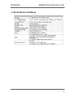
Page 5: ...ator Input Optional Resistive Touchscreen Power 85 to 230 VAC auto ranging Operating Temperature 32 F to 122 F 0 C to 50 C Operating Humidity 5 to 80 RH non condensing Vibration 5 Hz to 500 Hz 1 G Sho...

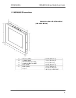
Page 6: ...s Isometric view with dimensions see table below A Chassis Width 17 26 438 4 mm B Chassis Height 15 00 381 0 mm C Chassis Depth including power connector module 4 13 104 9 mm D Bezel Width 18 25 463 6...

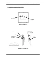
Page 7: ...Screen Monitor User s Guide 7 1 4 MON 920 Supplementary Views MON 920 Rear View MON 920 Top and Side Views Adjustment Controls Chassis Fan Video Connector Optional Serial Touch Connector AC Power Conn...

Page 8: ...VAC power connector is located on the right side panel of the unit as shown in the side views figure This module is rated only for non hazardous locations See section 3 2 on page 9 for power up inform...

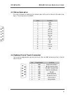
Page 9: ...Ground 7 Ground 8 Ground 9 N C 10 Ground 11 N C 12 N C 13 H Sync 14 V Sync 15 N C 2 4 Optional Serial Touch Connector If your unit is equipped with serial resistive touch this mini DB9 connector will...

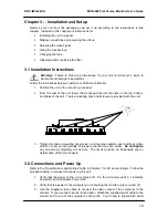
Page 10: ...unit Twelve mounting clips and screws are provided with the unit 3 Tighten the twelve mounting clip screws in a criss cross pattern each a little at a time until five to seven inch pounds of torque is...

Page 11: ...wings in sections 1 4 2 3 and 2 4 4 Plug the supplied AC power cord into an outlet and then into the AC Power Connector socket on the side of the flat screen monitor refer to the Side View drawings in...

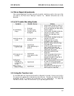
Page 12: ...ents Unrecognizable sync patterns Reset the factory default settings see Appendix Verify the supplied video format The monitor recognizes only 640x480 800x600 1024x768 1280x1024 PC formats LCD image i...

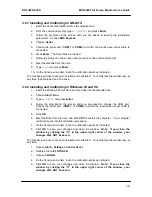
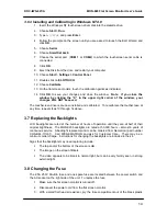
Page 13: ...ndows 95 touchscreen driver disk into the diskette drive 2 Choose Start Run 3 Type A SETUP and press Enter 4 Follow the prompts on the screen until you are asked to choose the COM port Choose the seri...

Page 14: ...ate the touchscreen at any time repeat steps 10 through 14 above 3 7 Replacing the Backlights LCD backlights are rated at the number of hours of operation until they are at half of their original brig...

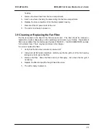
Page 15: ...ould be cleaned or replaced as needed depending on the operating environment in your facility Replacement filters are available from Nematron part number 272A0012 Call 800 NEMATRON and ask for Custome...

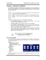
Page 16: ...tton when the option is highlighted To choose from a list of fixed values scroll through them by using the middle and bottom buttons and when the preferred choice is highlighted select it by using the...

Page 17: ...Lock that value in by pressing the top button 4 Repeat steps 1 to 3 to make other changes if desired 5 When you are finished use the middle or bottom button to highlight Return and press the top butt...

Page 18: ...pressing the top button 4 Repeat steps 1 to 3 to make other changes if desired 5 When you are finished use the middle or bottom button to highlight Return and press the top button to return to the mai...

Page 19: ...pixels x 1024 pixels flat panel display If you choose One to One AND the resolution on your computer is set to something less than 1280 x 1024 you will see a black band around your image because the M...

Page 20: ...gs and the selections Use the Horizontal and Vertical sliders under User Settings to adjust the position of the image on the display These settings are very stable and should not require adjustment af...

Page 21: ...le of the equipment identified below ________________________________________________________________ Equipment Class Information Technology Equipment Product Model Series MON 920 Analog Flat Screen M...

Reviews: