DOC-IWS-621/A
MON-920 Flat Screen Monitor User’s Guide
8
Chapter 2 -- Components, Connectors, and Pinouts
This chapter describes the components and connectors of your flat panel monitor.
Warning!
Make sure your monitor is powered down and unplugged before
removing the cover or working on internal components.
Warning!
Make sure your monitor is grounded at all times. Also make sure that it
is on the same ground as any other equipment connected to its communications
ports.
2.1 AC Power Connector and Switch
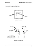
The 110/220 VAC power connector is located on the right side panel of the unit, as shown in
the side views figure. This module is rated only for non-hazardous locations. See section 3.2
on page 9 for power up information.
On the AC power switch, “1” indicates P
ower ON
and “0” indicates
Power OFF
.
If necessary, the 2.5A 250V Slo-Blo fuse can be replaced according to the instructions given
in section 3.8 on page 12.
2.2 Cooling Fan
The fan which cools the unit is located on the rear panel, as shown in the rear view figure.
The fan housing is secured to the unit case with four Philips-head screws, and the fan filter is
located inside the housing. Clean or replace the fan filter as needed according to the
instructions in section 3.9.


