background image


11 

SERIAL

RS-232

VGA

USB

"B"

USB 

RETENTION 

BRACKET

DVI-D

TOUCH SCREEN 

CABLES

VIDEO CABLES

(AUTO ADJ)

MENU

DOWN

SELECT

UP

(VGA / DVI)

POWER


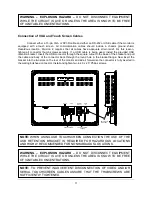
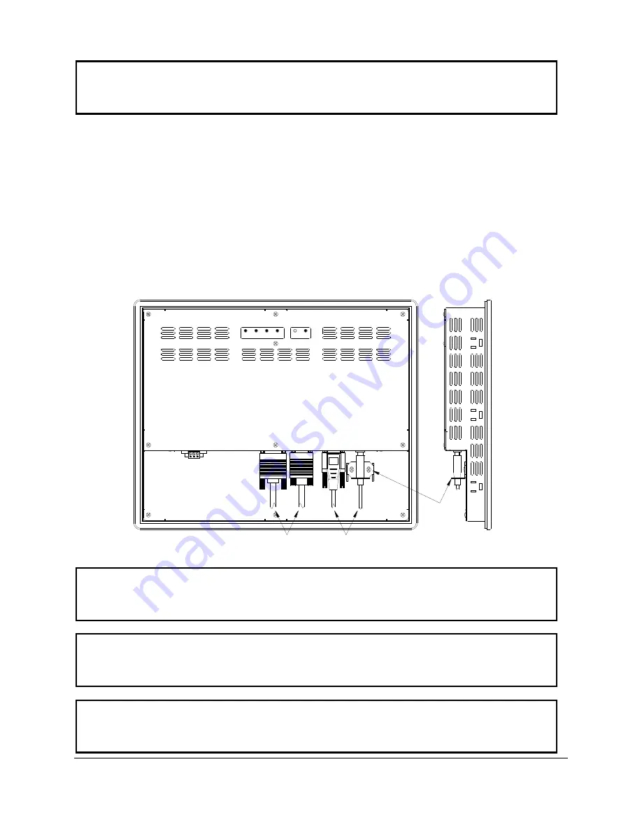
Connection of VGA and Touch Screen Cables 


Connect either a 15-pin VGA or DVI-D cable and either an RS-232 or USB cable if the monitor is 

equipped  with  a  touch  screen.  All  communication  cables  should  include  a  chassis  ground  shield.  
Hazardous  location,  Division  2,  requires  that  all  cables  have  adequate  strain  relief.  For  this  reason, 
tighten  all  connector  thumb  screws  securely.  If  a  USB  cable  is  being  used,  install  the  provided  USB 
retention bracket. Insert the USB connector through the square cutout in the base of the bracket and pull 
the  cable  and  body  of  the  connector  back  through  the  round  hole  in  the  bracket  flange.  Now  insert  the 
bracket into the two slots on the rear of the monitor and side it forward so the connector is fully inserted in 
the mating bulkhead connector. Install and tighten two 4-

40 x .25” Philips screws.  


NOTE: 

TO  PREVENT  INADVERTENT  DISCONNECTION  OF  VIDEO  AND/OR 

SERIAL  TOUCHSCREEN  CABLES  ASSURE  THAT  THE  THUBSCREWS  ARE 
SUFFICIENTLY TIGHTENED. 

WARNING 

–  EXPLOSION  HAZARD  –


DO  NOT  DISCONNECT  EQUIPMENT 

WHILE THE CIRCUIT IS LIVE OR UNLESS THE AREA IS KNOW TO BE FREE 
OF IGNITABLE CONCENTRATIONS. 

NOTE:


WHEN  USING  USB  TOUCHSCREEN  CONNECTION  THE  USE  OF  THE 

USB  RETENTION  BRACKET  IS  REQUIRED  FOR  HAZARDOUS  LOCATIONS 
AND HIGHLY RECOMMENDED FOR NONHARDAOUS LOCATIONS. 

WARNING 

–  EXPLOSION  HAZARD  –


DO  NOT  DISCONNECT  EQUIPMENT 

WHILE THE CIRCUIT IS LIVE OR UNLESS THE AREA IS KNOW TO BE FREE 
OF IGNITABLE CONCENTRATIONS. 
Summary of Contents for Nematron M1900

Page 1: ...Document No DOC IWS 714C Rel 6 2008 M1900 M1900T 19 0 XGA TFT NEMA 4 12 Flat Panel Monitor User s Guide User s Guide...

Page 2: ...been altered or modified in design or construction or which has been serviced by anyone other than Nematron The warranty set forth herein is in lieu of and exclusive of all other warranties express or...

Page 3: ...of VGA and Touch Screen Cables 11 Turning on the Computer and Monitor 11 Selection of PC Video Settings 12 Installing the Touch Screen Driver Software 12 Chapter 3 Monitor OSD and Settings 12 On Scree...

Page 4: ...vision 2 Groups A B C D and Class II Division 2 Groups F and G NEMA 4 4X 12 front bezel 2 Year warranty RoHS Compliant Integral 100 240 VAC power supply Simplified installation with no studs Thin desi...

Page 5: ...ns H x W 14 90 x 17 75 Weight 21 lbs Shipping Weight 26 lbs ELECTRICAL AC Input Voltage 100 240 VAC 50 60 Hz AC Input Current 1A Maximum DC Input Voltage Optional 18 36 VDC DC Input Current Optional 1...

Page 6: ...47 CFR Part 15 Class A EU CE Marking Compliance CE EN 55022 Class A EN 61000 3 2 Class A EN 61000 3 3 EN 61000 6 2 Safety Agency Approvals UL 508 Listed UL 1604 Listed cUL Listed CSA C22 2 142 CSA C2...

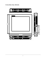
Page 7: ...7 2 1 3 18 66 2 70 15 70 2 95 1 50 6 00 Front and Side Views of Monitor...

Page 8: ...onitor is designed to work in environments up to 50 degrees Centigrade Remember to account for heat dissipated from other equipment that may be inside the same enclosure To install the monitor make a...

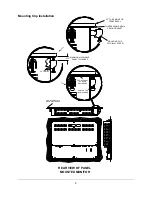
Page 9: ...TIGHTEN TO 8 INCH POUNDS COMPRESSABLE NEMA SEALING GASKET 25 THICK MONITOR FRONT BEZEL MAXIMUN ALLOWABLE PANEL THICKNESS CUT AWAY 325 FRONT PANEL OF NEMA ENCLOSURE MOUNTING CLIP WITH 10x32 SCREW Moun...

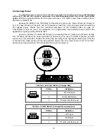
Page 10: ...on page 12 Consideration should be give to the installation of an appropriately rated external power switch if the application requires powering off the M1900 Power is connected to the M1900 through...

Page 11: ...nd body of the connector back through the round hole in the bracket flange Now insert the bracket into the two slots on the rear of the monitor and side it forward so the connector is fully inserted i...

Page 12: ...video settings match the native resolution of the M1900 s LCD For this reason it is recommended that you set the video mode to 1280 x 1024 with a screen refresh rate of 60 Hz This can be done using Wi...

Page 13: ...P Chapter 3 Monitor OSD and Settings On Screen Display OSD Controls The OSD controls are used for making adjustments to the monitor s settings and are located on the back of the monitor They consist o...

Page 14: ...selects and deselects menu choices HOT KEY When the OSD is not displayed pressing this button will initiate an automatic configuration and cause the Processing Auto Configuration message to be displa...

Page 15: ...atively it will turn off after a time out period that is set in the SET UP sub menu Finally it can be turned off by pressing the DOWN button to move the blue highlighted band down to the EXIT sub menu...

Page 16: ...elect this function causing the following screen to appear CONTRAST Pressing the DOWN button once and the SELECT button once will cause the following screen to appear Pressing the UP and DOWN buttons...

Page 17: ...and Down buttons to highlight PRESET1 or PRESET2 and press SELECT to make your selection and return to the MAIN MENU If you highlight RED GREEN or BLU and press select the following screen appears Pr...

Page 18: ...ressing SELECT will initiate an automatic configuration and cause the Processing Auto Configuration message to be displayed During the auto configuration process the monitor automatically centers the...

Page 19: ...SELECT will display the CLOCK adjustment menu Pressing UP increases the CLOCK and causes the screen to increase in width Pressing the DOWN button causes the CLOCK to decrease and the screen to reduce...

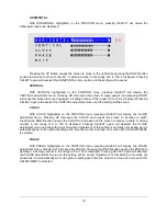
Page 20: ...P U T S O U R C E P C E X I T With the OSD POSITION highlighted on the SETUP menu pressing SELECT will cause the following screen to be displayed O S D P O S I T I O N 3 O S D T I M E 2 0 S E C L A N...

Page 21: ...ustment of the OSD time out setting in the range from 5 to 60 seconds Pressing SELECT again will deselect the OSD TIME menu and save the current setting LANGUAGE With LANGUAGE highlighted on the SETUP...

Page 22: ...O S D P O S I T I O N 3 O S D T I M E 2 0 S E C L A N G U A G E E N G L I S H I N P U T S O U R C E P C E X I T Pressing the UP and DOWN buttons switches between PC the 15 pin analog VGA input connect...

Page 23: ...no incoming video signal is detected immediately following self diagnostics the following message will appear This message will remain displayed indefinitely until a valid signal is detected The LED...

Page 24: ...SAVER MODE message indicates the monitor is setup to receive incoming video through the 15 pin analog VGA input connector The DIGITAL POWER SAVER MODE message indicates the monitor is setup to receive...

Page 25: ...ive Signal 10 TMDS DATA1 TMDS DATA1 Differential Positive Signal 11 TMDS DATA1 Shield Shield for TMDS Channel 1 12 N C No Connection 13 N C No Connection 14 5V Power 5 Volt signal for EDID 15 GND 5V R...

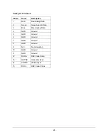
Page 26: ...Data 2 Green Green Analog Data 3 Blue Blue Analog Data 4 GND Ground 5 GND Ground 6 GND Ground 7 GND Ground 8 GND Ground 9 N C No Connection 10 GND Ground 11 GND Ground 12 DSDA DDC Serial Data 13 HSYNC...

Page 27: ...5 GND Ground 6 DSR Data Set Ready 7 RTS Request To Send 8 CTS Clear To Send 9 RI Ring Indicator USB Pin No Name Description 1 VBUS 5V Power 2 USB_D USB Data 3 USB_D USB Data 4 GND Ground Note The touc...

Reviews: