background image

Part  2  Technical  Manual  Of  Motherboard 

20 

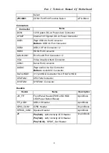
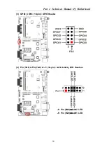
(3)  GPIO_CON1 (10-pin): GPIO Header 


(4)  Pin( 5&6) & Pin(7&8) of J1 (12-pin): LAN Activity LED Headers 


J1: Pin (5&6)

LAN2 LED   

J1: Pin (7&8)

LAN1 LED


Summary of Contents for Smart T8000

Page 1: ...Smart T8000 Intel Bay Trail Series CPU Fanless Embedded System User s Manual Revision 2 0 Release date July 20 2018...

Page 2: ...gram 9 2 2 Hardware Installation 13 2 2 1 Jumper Setting 13 2 2 2 Connectors and Headers 16 2 3 Introducing BIOS 21 2 3 1 Entering Setup 22 2 3 2 BIOS Menu Screen 23 2 3 3 Function Keys 23 2 3 4 Getti...

Page 3: ...ot be construed as a commitment by manufacturer Environmental Protection Announcement Do not dispose this electronic device into the trash while discarding To minimize pollution and ensure environment...

Page 4: ...or may decrease the life of computer Using the close case may decrease the life of other device because the higher temperature in the inner of the case Attention to the heat sink when you over clockin...

Page 5: ...trademarks or copyrights of their respective companies and they are used only for identification or explanation and to the owner s benefit without intent to infringe Manual Revision Information Revers...

Page 6: ...Part 1 Specification of Smart T8000 5 Part 1 Specification of Smart T8000 1 1 Overview Fig 1 1 Smart T8000 Fig 1 2 Smart T8000 Rear Fig 1 3 Smart T8000 Front 8 COM...

Page 7: ...T8000 Specification Type Smart T8000 CPU Default Configuration Intel Celeron Processor J1900 2 0GHz up to 2 41GHz 2M Cache On Board Memory Capacity 4GB DDR3L SODIMM Max 8GB Storage Default Configurat...

Page 8: ...or 8 VGA 1 HDMI 1 Audio 1 Line Out 1 Mic KB MS Port USB Display Video Memory On board Monitoring Watchdog 0 255 Seconds Power Default Configuration DC12V Lockable input 90 240VAC output 12VDC 5A 60W...

Page 9: ...port CPU Over Current Under Voltage protection Amplifier implement to support 3W Speaker Support CPU Smart FAN Compliance with ErP standard Support Watchdog function 2 1 2 Motherboard Specification Sp...

Page 10: ...MIC port Internal I O 1 2 Pin internal 12V DC in power connector 1 CPUFAN header 1 SYSFAN header 1 Front panel header 1 4 pin USB 2 0 header Expansible to 1 USB 2 0 port 1 GPIO_CON header 1 SPEAK_CON...

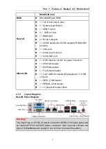
Page 11: ...10 Motherboard Internal Diagram Front Side Note 1 The memory module should be DDR3L 1 35V SODIMM and not exceeding 8GB total capacity 2 SIM card slot only work when compatible SIM card installed 3G LA...

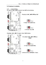
Page 12: ...sible harm Make sure that there is no damage to the CPU during any installation procedures Jumper Jumper Name Description JBAT_MERTC Pin 1 3 Clear ME Function Setting Pin 2 4 Clear CMOS RAM Function S...

Page 13: ...Connector 2 VGA Video Graphic Attach Connector COM1 Serial Port Connector AUDIO Top Audio Line Out Connector Bottom Audio MIC Connector SATA HDD1 3 7 pin HDD Connector for 2 5 SATA HDD CPUFAN1 CPUFAN...

Page 14: ...per Setting Pin 1 3 of JBAT_MERTC 4 pin Clear ME Function Setting Pin 1 3 of JBAT_MERTC Clear ME 1 3 Open Normal Default 1 3 Closed Clear ME Pin 2 4 of JBAT_MERTC 4 pin Clear CMOS Setting Pin 2 4 of J...

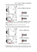
Page 15: ...d Press power button to power on after power input ready AT Mode Selected Directly power on as power input ready Pin 3 4 of J1 12 pin Case Open Message Display Function Select Pin 3 4 of J1 Case Open...

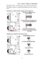
Page 16: ...orm you of this Pin 9 10 of J1 12 pin ME Security Measure Function Select Pin 9 10 of J1 ME Security Function Select 9 10 Open Enable Security Measures in the Flash Descriptor Default 9 10 Closed Disa...

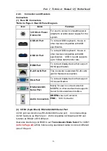
Page 17: ...that support HDMI specification RJ 45 LAN Port This connector is standard RJ 45 LAN jack for Network connection VGA Port To connect display device that support VGA specification RS232 422 485 Serial P...

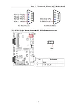
Page 18: ...Part 2 Technical Manual Of Motherboard 17 For RS422 Mode For RS485 Mode 3 ATX2P 2 pin Block Internal 12V DC in Power Connector Pin Definition 1 GND 2 12V DC_IN...

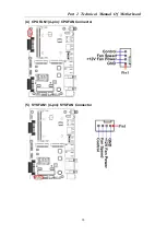
Page 19: ...Part 2 Technical Manual Of Motherboard 18 4 CPUFAN1 4 pin CPUFAN Connector 5 SYSFAN1 4 pin SYSFAN Connector...

Page 20: ...Part 2 Technical Manual Of Motherboard 19 Headers 1 JW_FP 9 pin Front Panel Header 2 FP_USB1 4 pin USB 2 0 Port Header...

Page 21: ...Part 2 Technical Manual Of Motherboard 20 3 GPIO_CON1 10 pin GPIO Header 4 Pin 5 6 Pin 7 8 of J1 12 pin LAN Activity LED Headers J1 Pin 5 6 LAN2 LED J1 Pin 7 8 LAN1 LED...

Page 22: ...PDIF Out Header J1 Pin 11 12 SPDIF_OUT Header 6 SPEAK_CON1 4 pin Speaker Header Pin No Definition 1 L 2 L 3 R 4 R 2 3 Introducing BIOS Notice The BIOS options in this manual are for reference only Dif...

Page 23: ...e synchronization Only when these tasks are completed done it gives up control of the computer to operating system OS Since the BIOS is the only channel for hardware and software to communicate it is...

Page 24: ...step in the following pages of this chapter but let us first see a short description of the function keys you may use here Press left right to select screen Press up down to choose in the main menu th...

Page 25: ...2 3 5 Menu Bars There are six menu bars on top of BIOS screen Main To change system basic configuration Advanced To change system advanced configuration Chipset To change chipset configuration Securit...

Page 26: ...Part 2 Technical Manual Of Motherboard 25 System Date Set the date Please use Tab to switch between data elements System Time Set the time Please use Tab to switch between time elements...

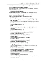
Page 27: ...PI Settings Press Enter to make settings for the following sub item ACPI Settings ACPI Sleep State Use this item to select the highest ACPI sleep state the system will enter when the suspend button is...

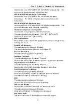
Page 28: ...Control When set as Enabled the following sub items shall appear WatchDog Timer Value User can set a value in the range of 10 to 255 WatchDog Timer Unit The optional settings are Sec Min WatchDog Wak...

Page 29: ...ata Bits The optional settings are 7 8 Parity The optional settings are None Even Odd Mark Space Stop Bits The optional settings are 1 2 Flow Control The optional settings are None Hardware RTS CTS VT...

Page 30: ...or may not show up depending on different configuration Parity The default setting is None This item may or may not show up depending on different configuration Stop Bits The default setting is 1 This...

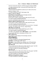
Page 31: ...Limit CPUID Maximum The optional settings Disabled Enabled This item should be set as Disabled for Windows XP Execute Disable Bit The optional settings Disabled Enabled Hardware Prefetcher The optiona...

Page 32: ...Disabled When set as Enabled the following sub items shall appear Ipv4 PXE Support The optional settings are Disabled Enabled Use this item to enable Ipv4 PXE Boot Support When set as Disabled Ipv4 bo...

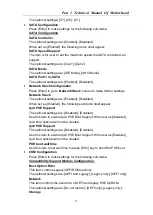
Page 33: ...ttings range is from 1 60 minute s USB1 Wake up from S3 S4 Use this item to enable or disable USB Wake up from S3 S4 The optional settings Disabled Enabled This item is only supported when ERP Support...

Page 34: ...et value for the following sub item Device Power up Delay in Seconds Device Power up Delay in Seconds The delay range is from 1 to 40 seconds in one second increments Intel R I211 Gigabit Network Conn...

Page 35: ...pre allocated fixed graphics memory size used by the internal graphics device The optional settings are 64M 96M 128M 160M 192M 224M 256M 288M 320M 352M 384M 416M 448M 480M 512M DVMT Total Gfx Mem Use...

Page 36: ...Disabled Azalia will be unconditionally disabled Enabled Azalia will be unconditionally enabled Azalia Internal HDMI Codec Use this item to enable or disable internal HDMI codec for Azalia The option...

Page 37: ...Part 2 Technical Manual Of Motherboard 36 2 3 9 Security Menu Security menu allow users to change administrator password and user password settings...

Page 38: ...umber of seconds to wait for setup activation key Bootup Numlock State Use this item to select keyboard numlock state The optional settings are On Off Quiet Boot The optional settings are Disabled Ena...

Page 39: ...tem to restore load default values for all the setup options Save as User Defaults Use this item to save the changes done so far as user defaults Restore User Defaults Use this item to restore the use...

Page 40: ...ports Adapter 3 1 1 Feature of Four COM ports Adapter Dimension 64 5mm 74mm Chipset FT81504 PCIe Gen 1 1 TO 4 UART Feature Support 4 UART COM ports COM1 4 support RS4232 22 485 function Interface PCIe...

Page 41: ...M4 COM4 Port Pin 9 1 3 4 6 2 6 4 2 5 3 1 6 4 2 5 3 1 5 2 4 Closed Pin9 RING Default 3 4 Closed Pin9 5V 4 6 Closed Pin9 12V JCOM1 Select RS232 RS422 RS485 for COM1 port JCOM2 Select RS232 RS422 RS485 f...

Page 42: ...s 10 Mbps RS485 RS422 Connector Pin Definition COM1 2 3 4 RS232 Pin No Pin Definition Pin No Pin Definition 1 DCD 6 DSR 2 SIN 7 RTS 3 SOUT 8 CTS 4 DTR 9 RI 12V 5V 5 GND RS422 Pin No Pin Definition Pin...

Page 43: ...Chipset Pericom PI7C9X2G608GP PCI Express Gen 2 Switch Intel i211AT PCIe GbE LAN Feature PCIex1 interface supports any of Motherboard with PCIe slot 4 Intel i211AT PCIe GbE LAN Support Wake on LAN S1...

Reviews: