background image

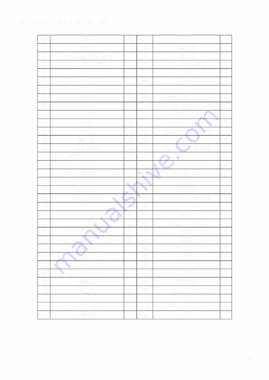
Table of Components 

No. 

Parts 

Q'ty 

No. 

Parts 

Q'ty 

SCREW 

34 

0-RING

COMPRESSION SPRING 

35 

BUSHING 

RELIEF VALVE PIN 

36 

MOTOR & GEAR SET 

RELIEF DEVICE 

37 

BLOCKER 

RELIEF VAL VE TOP 

38 

SCREW 

0-RING

39 

PIN 

SCREW 

40 

TORSIONAL SPRING 

CYLINDER 

41 

RELEASE  LEVER 

COMPRESSION SPRING 

42 

RELEASE TRIGGER 

10 

BALL 

43 

ADVANCE TRIGGER 

11 

0-RING

44 

COMPRESSION SPRING 

12 

SCREW 

45 

SCREW 

13 

OIL SCREEN 

46 

COMPRESSION SPRING 

14 

PUSH IN FASTNER 

47 

HOUSING 

15 

BALL 

48 

SPRING WASHER 

16 

COMPRESSION SPRING 

49 

SCREW 

17 

SCREW 

50 

PISTON 

18 

DUST SEAL 

51 

DUST SEAL 

19 

BACK-UP RING 

52 

COMPRESSION SPRING 

20 

SCREW 

53 

CYLINDER COVER 

21 

COMPRESSION SPRING 

54 

SCREW 

22 

PLUNGER 

55 

TORSIONAL SPRING 

23 

COMPRESSION SPRING 

56 

YOKE 

24 

0-RING

57 

LATCH 

25 

BACK-UP RING 

58 

DIE SIZING LOCK PIN 

26 

SCREW 

59 

PIN 

27 

RELEASE VALVE STEM 

60 

DIE HOLDER 

28 

BALL 

61 

HINGE PIN 

29 

SCREW 

62 

CRESENT 

30 

0-RING

63 

BALL PLUNGER 

31 

SCREW 

64 

SCREW 

32 

OIL RESERVOIR 

65 

COMPORESSION SPRING 

33 

0-RING

66 

PCB 

17 

Summary of Contents for NMBT240

Page 1: ... Battery Operated Crimper NMBT240 Version 2019 05 Battery Operated Crimpers are inspected for guality and tested for safety We follow ISO 9001 2015 ISO i4001 2015 IECQ QC 080001 OHSAS 18001 2007 TTENTION Safe Operation Maintenance lnstructions must be followed Recommend for indoor use ...

Page 2: ......

Page 3: ......

Page 4: ......

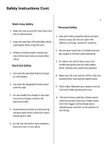
Page 5: ... the reach of children All usersshould be familiar with its use before operating 6 Store the battery away from materials which may short the battery and cause a hazard 7 lnspect the tool before and after every use Do not use this tool if it is damaged in any way 8 Personal injury can be caused by operating poorly maintained tools Check for loose parts before using 9 Use only manufacturer recommend...

Page 6: ......

Page 7: ......

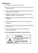
Page 8: ...ic tools must be serviced by a qualified technician Contact our representative for more information TTENTION Do not dispose of electrical appliances as unsorted municipal waste Use separate collection facilities lf electrical appliances are disposed of in landfi 1s or dumps hazardous substances can leak into the groundwater damaging the public s health and we 1 being Contact your local government ...

Page 9: ... after 10 seconds once the tool is not in operation mode The battery light indicate the batte1ry level voltage or abnorma problem with the tool 1 Once the red light is flushing it indicates there is a problem with the tool 2 Once the red light is on it indicates no battery and can t be operate 3 The battery level can also be check at the back of the battery ...

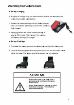
Page 10: ...tridge is approx 35 minutes When stored in the charger the battery will stay fully charged Battery Cartridge 1 To release the battery press on the battery latch and pull the battery out 2 To install the battery slide the battery into the base of the tool handle until it clicks into place The battery should be secured and unmoveable ATTENTION Remove the battery cartridge before exchanging the tool ...

Page 11: ... should be secured and unmoveable 2 Press the release bottom to release the the hydraulic pressure in the tool The tool is ready to use when the piston returns to the starting position 3 Pull back the lactch to open the head The head will spring open 4 Slide the dies inta the open head Make sure the dies are matching and seated correctly ...

Page 12: ...re the tool in its case with the cylinder piston fully retracted TTENTION Do not put your fingers through the crimping area of the crimper to remove the cable when the battery pack is in place and you are holding the tool with you other hand Pay attention The piston and indenters advance quickly lf the trigger is accidentally pressed it can result in severe damage to your hand For your safety remo...

Page 13: ......

Page 14: ......

Page 15: ......

Page 16: ......

Page 17: ......

Page 18: ...6 COMPRESSION SPRING 1 14 PUSH IN FASTNER 2 47 HOUSING 1 15 BALL 2 48 SPRING WASHER 2 16 COMPRESSION SPRING 2 49 SCREW 2 17 SCREW 2 50 PISTON 1 18 DUST SEAL 2 51 DUST SEAL 1 19 BACK UP RING 2 52 COMPRESSION SPRING 1 20 SCREW 2 53 CYLINDER COVER 1 21 COMPRESSION SPRING 2 54 SCREW 1 22 PLUNGER 2 55 TORSIONAL SPRING 2 23 COMPRESSION SPRING 1 56 YOKE 1 24 0 RING 2 57 LATCH 1 25 BACK UP RING 1 58 DIE S...

Page 19: ......

Reviews: