background image

1).Ensure the voltage systems of the wind generator and the battery bank are 
the same. Prepare the appropriate wires.

2).Run the wire through the pipe and drag the wires near to the batteries 
(Do not connect to the battery), strip the insulation back from each set of wires.

battery

5) Prepare a grounding cable from yaw shaft screw, secure the grounding 
cable against the pipe with insulation tape for grounding the wind 
generator by the pipe.

3).Connect the Wind Generator to the wires and insulate the connections 
using either heat shrink tubing or a quality electrical tape.

4).Once the yaw shaft is on the tower, firmly tighten the yaw clamp screws with
the 4mm hex key to 3-5 foot pounds(4.0-6.5Nm). Be sure that it is securely 
attached to the mounts.
Slide the yaw shaft all the way down over the end of pole being careful not to 
pinch the yaw wires. Be sure to leave enough slack in the wires so that if 
necessary, the Wind Generator can be removed.

12

6.5 Step-by-step instructions

outline of the Marine grade 400


Watt wind turbine.

Summary of Contents for FSH400

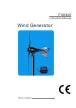
Page 1: ...Instruction Manual FSH400 Wind Generator Serial number...

Page 2: ...prior notice Therefore check the website for updates as necessary The 400 Watt Wind Turbine like other sources of electrical power must be installed following the guidelines established by state and l...

Page 3: ...em wiring diagrams 4 LOCATION SELECTION 5 TOWER 6 1 SINGLE WIND GENERATOR 6 2CONTROLLER WIRING 6 3 INSTALLATION OPERATION 6 4 ATTACHING TO POLE 6 5 STEP BY STEP INSTRUCTION 7 WARRANTY POLICY 7 1 ELEVA...

Page 4: ...rical dangers The internal electronics of the Wind Turbine prevents open circuit voltages from rising above 20 volts for 12 volt systems Please note that the inherent personal dangers from electrical...

Page 5: ...ine yaw and the turbine rotor will require approximately 60 100 hours of operation in normal wind speeds approximately 18 20 mph 8 9 m s before they are running at peak efficiency During this break in...

Page 6: ...or 1 4 6 7mm heat shrink not included Wire strippers not included Wire crimpers not included NOTE Do not connect to the battery Precheck Spin rotor shaft slowly with your fingers while at the same ti...

Page 7: ...bulence Smooth laminar airflow 2H 20H Turbulent airflow 2H H Turbulent airflow created by obstructions Ad P Gipe 93 Therefore as a general rule the Wind Generator should be mounted twice as high as an...

Page 8: ...cost and effort of the installation This Wind Generator is designed to use steel pipe 1 875 inch 48mm outside diameter equivalent to 1 inch SCH 40 pipe which can be used in some tower applications If...

Page 9: ...op Rotor rotating at low spin or stop Rotor rotating at low spin or stop rotation and stop suddenly Rotor rotating at 500 1400rpm Battery fully charged voltage exceeds14 2V Over speed Rotor rotating o...

Page 10: ...negative and negative to positive or else will damage the controller Red is for positive Black is for negative Note 3 red wires from turbine can be placed in any order to controller AC input terminal...

Page 11: ...CAREFULLY NOTE DO NOT install the blade assembly until the body is mounted on the tower CAUTION ALL BATTERIES MUST DISCONNECTED THROUGHOUT THE INSTALLATION PROCESS CAUTION DO NOT INSTALL THE WIND GEN...

Page 12: ...d generator by the pipe 3 Connect the Wind Generator to the wires and insulate the connections using either heat shrink tubing or a quality electrical tape 4 Once the yaw shaft is on the tower firmly...

Page 13: ...blades assembly onto the rotor shaft and place the nut on the shaft DO NOT press the rotor shaft into the body Caution over torque will damage the blades and wind generator M16 NUT 8 Insert the 8mm he...

Page 14: ...egative wire of your system should be connected to a ground This is usually done by connecting a wire from the negative battery terminal to a nearby ground rod Wires with the same ratings as the posit...

Page 15: ...7 000 8 000ft 8 000 9 000ft 9 000 10 000ft 150 300m 300 600m 600 900m 900 1 200m 1 200 1 500m 1 500 1 800m 1 800 2 100m 2 100 2 400m 2 400 2 700m 2 700 3 000m 97 94 91 88 85 82 79 76 73 70 7 1 ELEVATI...

Page 16: ...FSH 8 SPECIFICATIONS 839290007068 FSH400 Marine grade 400 Watt Wind turbine DC12V or DC24V...

Reviews:

Related manuals for FSH400