7.
Download and save the NEMTEK SIO8Cfg setup software from:
http://nemtek-druid-
fenceprobe.com/downloads/NemtekSmartIOCardConfigurationSoftware.exe
8.
Power up the board (The NEMTEK Power Pack can be used to power the board).
9.
Open the NEMTEK SIO8Cfg.exe application on the computer
10.
Select the device (Druid 2x, TW Node or 8-way Relay Board) to which the Smart IO board will be
connected to by clicking on one of the three top tabs.
11.
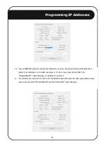
Enter the same IP address (Static IP) of the Smart IO board that was configured in step one, in the
IP address field, in the top right corner.
12.
Ensure 20108 is entered in the Port field, in the top right corner.
13.
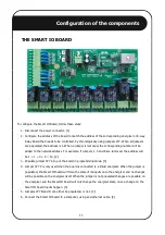
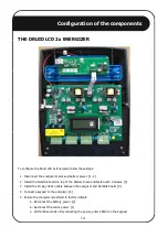
If the Smart IO board will be connected to an energizer, map the energizer status and alarms to the
Smart IO relay outputs, by ticking appropriate boxes. The Smart IO Board Inputs are preconfigured
to activate certain functions on the energizer and can’t be changed. Input 1 is zone 1 On/Off, input
2 is zone 2 On/Off, input 3 is zone 1 Hi/Low voltage and input 4 is zone 2 Hi/Low voltage.
14.
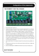
If the Smart IO board will be connected to an 8-way Relay Board, map the 8-way Relay Board inputs
to the Smart IO relay outputs, by ticking the appropriate boxes. The Smart IO board inputs are
configured one-to-one to the 8-way Relay Board’s outputs and can’t be changed. So input 1 of the
Smart IO board controls relay 1 of the 8-way Relay Board and input 2 controls relay 2 of the 8-way
Relay Board etc.
15.
Click Send in the lower left corner. The VALID COMMAND LED will momentarily flash on the Smart
IO Board, indicating the board was programmed. [5]
16.
Remover jumper JP7 A. [3]
17.
Disconnect the board from the computer and connect to the energizer, relay card or ethernet switch
with an ethernet cable.
Configuration of the components
12


