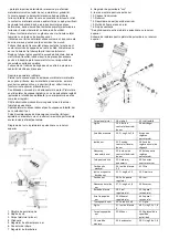
1. Lever "on/off"
2. Nozzle head
3. Pistol body (grip)
4. Hanger
5. Air supply regulator
6. Input connector
7. Spray rate controller
8. Spray "cone" regulator
9. Nozzle head mounting ring
10. Tank lid
11. Reservoir
12. Air vent (small hole)
13. Tank fixing nut
14. Vent plug
*Applies only to a spray gun with a top tank.
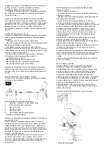
Installation diagram for a spray gun with a top tank
Pistol body
18. gasket 3
35. flexible stem
Gasket
19. air flow control
spring
36. arbor
Sealing screw
20. O-ring 2.5x1.8
Firing pin
adjustment spring
Air ring
21. air flow control
socket
38 Firing pin
adjustment socket
Nozzle seat seal
22. air flow control
knob
39 Firing pin
adjustment knob
Nozzle socket
23. Air coupling
40. Tank
connector
Material nozzle
24. Locking ring
3.5
41. filter
Air nozzle spring
ring
25. O-ring 8 x 1.5
42. Gasket
Air nozzle
26. regulator
socket
43. nit
Air nozzle seal
27. O-ring 6 x 1.8
44 Tank
Locking knob
28. regulator pin
45. tank lid
Air valve spring
29 Regulator knob
46. Tank lid cap
Air valve stem
30. Screw M4 x 8
47. Gasket
Gasket
31. Locking ring 4
48. O-ring 7.5 x 1.8
Air valve body
32. Handle
49. PE foam pad
16. sealing screw
33. trigger
50. O-ring 2.8 x 1.8
17. air flow control
pin
34 Trigger pin
*Applies only to spray guns with a top tank.
Commissioning and use
1.Tighten the reservoir (11) to the gun body with the screw (13).
2.Ensure that the vent hole (12) in the cover (10) is clean and
unobstructed and close it with the plug (14). An obstructed vent
will prevent operation - the plug has a small gap for vent operation.
3.Fill the container (11) with varnish and tighten the lid (10).
4.Connect the spiral hose supplying the gun with air to the input
fitting (6) and adjust the maximum pressure on the compressor to
4 Bar. The regulator (5) can be used to reduce the air pressure in
the gun if required - i.e. below 4 Bar.
5.By turning the intensity regulator (7), adjust the spray rate of the
paint material (tighten the regulator if you are using more liquid
paints, loosen the regulator if you are using thicker paints. Then,
by turning the regulator, the spray "cone" (8), adjust the spread of
the spray.
6.With the lever (1) engaged, the position of the "nozzle head" (2)
can be adjusted by slightly loosening the ring (9), changing the
shape of the spray. Always remember to tighten the ring (9)
correctly before starting work.
Spray intensity adjustment:
Adjustment of the spray 'cone':
7.Orient the nozzle head (2) perpendicular to the paint surface.
8.Before actual use, test on substitute material until optimum
results are obtained. Never leave paint material in the spray gun
tank for later use, as the instrument can be damaged beyond
repair in its precision parts.
9.After use, always clean the inside of the machine thoroughly by
filling the tank with clean thinner suitable for the paint material
used and start spraying without contaminating the environment
(spray in the direction of the rag or towards the absorbing
surface). Carry out cleaning until there are no traces of the used
paint material in the escaping thinner stream. This procedure
should also be followed if the nozzle is found to be blocked. Using
a rag soaked in thinner, clean the outside of the gun where it is
contaminated with the paint material used. For more thorough
cleaning, carefully disassemble the gun with the enclosed brush.
Soak all internal components for a few hours in a tank filled with
Summary of Contents for 14-700
Page 10: ...1 2 3 4 5 6 7 8 9 55 30 3...
Page 11: ...1 2 3 4 5 6 1 2 3 4...
Page 25: ...1 2 3 4 5 6 7 8 9 55 30 m3 PVC...
Page 26: ...1 2 3 4 5 6 1 2 3 4 5 6 7 8 9 10 11 12 13 14...
Page 28: ...9 GTX 2 5 m s2 EN 1953 1998 A1 2009...
Page 37: ......


