CHAPTER 4. OMNI DRIVE MODULE
4.4. ELECTRICAL INSTALLATION
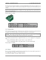
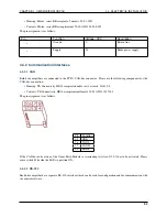
Pin
Function
Description
1
GND (Orientation)
Reference ground line (orientation drive)
2
TxD (Orientation)
Transmit line (orientation drive)
3
RxD (Orientation)
Receive line (orientation drive)
4
GND (Traction)
Reference ground line (traction drive)
5
TxD (Traction)
Transmit line (traction drive)
6
RxD (Traction)
Receive line (traction drive)
4.4.3 Digital-I/Os
The drive amplifiers each feature 6 digital inputs, 2 digital outputs and 1 analogue input which may be used for special
functions if required. They can be assigned to predefined functions (torque off, hard stop, etc.) or be accessed by the
user program running on the amplifier. Their current state can also be read by the control software via the CAN-bus
or the serial interface.
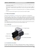
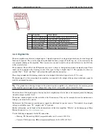
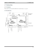
The connectors X2 and X5 of the PCB provide easy access to three of the digital inputs and one digital output. These
inputs can be equipped with a limiting resistor if the signal voltage is higher than 5 V. The positions for these are
marked “Rin1”, “Rin2” and “Rin3” and are located right beside the connectors.
Please keep in mind that the limiting resistor has to be bridged if the default signal level of 5 V is used.
The digital input 1 of the orientation drive amplifier is connected to the output of the position switch and cannot be
used for customised functions.
Tip:
The ground line of the digital inputs of the orientation drive amplifier is by default tied to the common ground
of the amplifier power supply. In case independent voltage levels are required, please contact Neobotix.
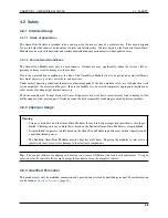
The return line of the digital inputs of the traction drive amplifier can also be tied to the common ground by bridging
the solder jumper marked “G
I-”.
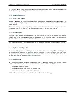
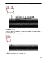
The motors’ encoder signals are also available at the IO connectors. They can for example be used for motion moni-
toring by an external safety device.
Furthermore the IO connectors provide power supply for additional low power sensors. The module’s logic supply
voltage is available at pins “VL” (supply) and “G” (ground).
Further information can be found in the documentation of the drive amplifier “Whistle” on the homepage of Elmo
Motion Control at
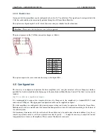
Use the following components for the I/O connection:
• Housing: TE Connectivity, HE14 receptacle double row 12 circuits, 281839-6
• Contacts: TE Connectivity, HE14 crimp terminal female 28-24 AWG, 182734-2
53

