CHAPTER 3. OMNI DRIVE MODULE
3.4. ELECTRICAL INSTALLATION
The internal logic unit of the drive amplifiers can be powered independently from the main power supply. In case of
an emergency stop the amplifiers will still be running, keeping track of the motor position and communicating on the
CAN-bus.
Tip:
By default the Omni-Drive-Module is configured for 24 V logic supply voltage. Please contact Neobotix if you
want to use other supply voltages.
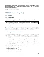
The pin assignment is as follows:
Pin
Function
Voltage / VDC
Description
1
Common ground
0
Common return line
2
Motor power supply
20 – 59
Main power supply, may be switched off
3
24V logic supply
11 – 30
Auxiliary supply, not to be switched at stop
3.4.1.2 Position Switch
If 24 V are used as logic supply voltage, the inductive position switch of the orientation drive is powered directly from
the amplifiers’ PCB. If different voltages are used, they must be connected to a common ground.
Attention:
The ground line of the digital input is by default connected to the common ground of the amplifier
power supply. In case independent supply voltages are required, please contact Neobotix.
Use the following components for the power supply of the switch in case you are not supplying 24 V for the amplifiers’
logic:
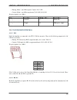
• Housing: Würth Elektronik, MPC4, receptacle, dual row, 2 circuits, 649002113322
• Contacts: Würth Elektronik, MPC4, crimp terminal female, 18-24 AWG, 64900613722DEC
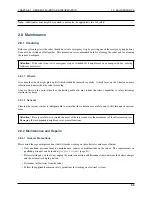
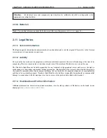
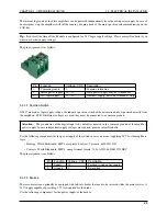
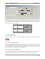
The pin assignment is as follows:
Pin
Function
Voltage / VDC
Description
1
Supply
24
Position switch power supply
2
Ground
0
Return line
3.4.1.3 Brakes
The servomotors can optionally be equipped with fail-safe brakes that need to be released while the motor rotates. A
24 V supply capable of providing 0.75 A is required for the brake.
Use the following components for the power supply of the brakes:
43

