17
Row panelized: several same PCBs are arranged in horizontal direction, and the nearby rows are mirrored
Column panelized: several same PCBs are arranged in vertical direction, and the nearby columns are mirrored
(2)Panelized Board Row and Column
The row and column are determined by the positioning of PCB on working area. The direction along the rails is the column,
the direction perpendicular to the rail is row, then please enter data in the row and column.
(
3
)
Please refer to the data collecting method of each position information as following:
After select the corresponding mirror board panelized method(column or row)and data of column&row,may occur the
situation of the align interface turn to gray and can’t be edited,then no need do position align.
Based on actual mirror board data,right side is showing corresponding images and can find the first component on it.
●
The data of “right top”on original board: on the alignment interface, find the right top panel that is nearest to the right
side but farthest to the feeding position, then find the first component which on the chip list of this panel, align the center of
this component, click save and cancel, it will return to the “PCB information” automatically.
●
The data of “left top”on original board: on the alignment interface,find the left top panel,then find the component same as
the component that aligned on the “right top”,align the center of this component, click save and cancel, it will return to the
“PCB information” automatically.
●
The data of “left bottom”on original board:on the alignment interface,find the left bottom panel,then find the component
same as the component that aligned on the “right top”, align the center of this component. After saving the data, it will
return to the “PCB information” automatically.
●
The data of “left bottom”on mirror board:on the alignment interface,find the left bottom panel,then find the component
same as the component that aligned on the “right top”, align the center of this component. After saving the data, it will
return to the “PCB information” automatically.
After setup, click “create panelized list”, the panelized list will be generated accordingly in the blank. You can also
double-confirm each position by clicking “Align”. Note:The angel difference between original and mirror board is 180
degree,original board is 0 degree,mirror is 180 degree.
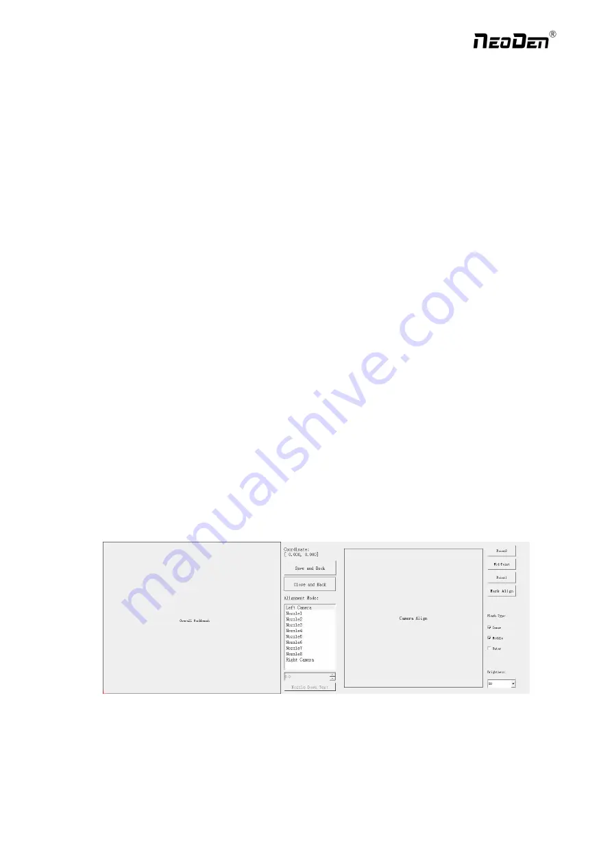
Introduction of Align interface:See below fig.
Save and Back:After align the center of components,click “save and back”to save the date.
Close and Back:Refer to exit the current interface.
Alignment Method:Include left mark camera,nozzle 1-8,right mark camera,choose the alignment method according to
the actual situation,right side will show the real image by mark camera alignment.
Zhejiang
NeoDen Technology Co.,Ltd.


